09 Electrical Features
General Information
There are two electrical systems in your motorhome. These are the 12 volt DC (VDC) system and the 120 volt AC (VAC) system. Most standard appliances require the 120 VAC system, while the majority of the lighting systems used in the motorhome use the 12 VDC electrical system.
The electrical power for the 12 VDC system is supplied by the batteries of the motorhome. Those batteries are charged by a power converter. The alternator also charges the batteries when the engine is running.
The electrical power for the 120 VAC is supplied by the power cord when the motorhome is connected to an external power source or when the on-board electrical generator is in operation. The converter/inverter can also supply 120 VAC electrical power (to limited outlets and limited appliances)— the inverter transforms the 12 VDC electrical power from the batteries into the 120 VAC electrical power for the basic appliances.
To connect the motorhome to an external source of 120 VAC electrical power, Tiffin Motorhomes recommends that all of the circuit breakers be in the OFF position, (this is done to prevent any power surge when connecting the motorhome to the external power source), and then unwind the power cord from the electrical compartment located in an external compartment. The standard, flexible, power cord supplied with the motorhome is designed to handle up to 50 amperes. Make sure that the pins in the male end of the plug are oriented correctly so that they match the power cable, and that they are in good condition (i.e., are not bent or damaged).
If there is a circuit breaker switch at the “plug” end of the power cord, that breaker must be turned OFF before making the connection. Insert the plug into the mating outlet, and then turn the circuit breaker ON. Close and lock the electrical compartment door to protect the contents and to keep them clean and dry. Close the cover on the power box, if so equipped, to avoid an unintentional disconnection and to keep the contents clean and dry. Then switch the main breaker to the ON position.
When properly connected, the 120 VAC system provides power to all the 120 VAC circuits and outlets when the main breaker is turned ON.
Electrical Cautions

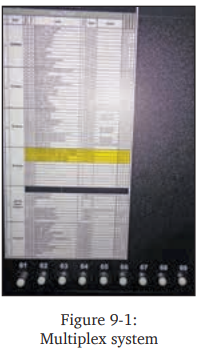
Multiplex System
The multiplex system (Figure 9-1) enables you to control circuits from multiple locations in the coach. Each switch enables you to turn a circuit ON or OFF with individual button presses, and provides an indicator light to determine the status of the circuit (ON or OFF).
Additional features of the multiplex system include the following:
Master Feature (this is only on the control panel located at the entrance door) — Enables you to turn all lighting circuits ON or OFF by pressing a single button labeled Light Master. Pressing the Light Master OFF switch will turn off all the interior lights within the coach. Momentarily pressing the Light Master ON switch will turn on the same circuits that were on when the Light Master OFF switch was pressed. Light Master OFF remembers which lights were on when the switch was pressed and will turn those same lights back on when the Light Master ON switch is momentarily pressed. Holding the Light Master ON switch will turn on all interior light circuits.
Switch Panel Backlighting — All of the switches are backlit to make the labels easy to read. If you desire to turn the panel lights OFF, a switch is conveniently located at the center of the coach labeled Panel Lights, which enables you to turn the back lighting ON, OFF, or DIM.
Status LED Indicator — A green LED beside each switch indicates whether the load is ON or OFF. In some cases, certain switches such as Awnings, Compartment Locks, and Generator do not have a status indicator at the switch.
Dimming Circuits — certain circuits within the coach are dimmable. To dim a light down, simply hold the “off ” switch until the light is at the desired level and release the switch. This setting will be remembered the next time the circuit is turned on. To adjust the light up, simply hold the “on” switch until the light is at the desired level and release the switch.
In the event that you have to check fuses, the centralized control panel is located in the third passenger side bay. The fuses for the different light circuits are located here. The status of a fuse for any circuit can be easily identified by looking at the circuit number and coordinating the number to the proper listing on the fuse list chart beside the centralized control panel.
If a circuit is on and the fuse is blown, the indicator light beside that fuse will be red. If the circuit is on and the fuse is good, the indicator light beside that fuse will be green. If the circuit is off, the indicator light beside that fuse will not be on.
Circuit Breaker Boxes
For the Phaeton, interior 120 VAC and 12 VDC breaker boxes (Figure 9-2) vary depending on your specific floorplan, however, in most floor plans, they are located in the rear closet.

The circuit breakers and associated fuses are installed to protect the electrical system of the motorhome from any overloads. Do not attempt to change the electrical circuitry or to add appliances yourself.
Consult an authorized Tiffin Motorhomes representative to determine whether any changes you desire are appropriate and acceptable.
The 120V breakers protect all appliances and 120V outlets in the motorhome, such as microwaves, air conditioners, washer and dryer, vacuum cleaners, etc.
Fusing is provided for the following 12 VDC circuits: all interior decorative and overhead lighting, water heater, TV switching box, slide-out lights, power roof vents, monitor panel, and the passenger side console switch panel.
Additional 12 VDC fuse panels are located in the front storage compartment on the driver’s side; these fuse panels provide protection for the following circuits: mirrors, fog lights, hydraulic jacks, camera, wipers, docking lights, dashboard panels, spot light, power seats, radio, step cover, satellite receiver, 30- ampere ignition breaker, 50-ampere ignition breaker, and dashboard air circuit breaker.
Auxiliary Start Switch
The auxiliary start switch (Figure 9-3) is located on the switch panel to the left of the steering wheel in front of the driver’s-side console box.

This switch connects the motorhome coach batteries to the chassis batteries—this allows the chassis batteries to “borrow” power from the coach batteries to assist in starting the engine.
If the chassis batteries cannot start the engine by turning the ignition key, hold down the battery-boost switch for at least 60 seconds and retry starting the engine.
When attempting to use the auxiliary start switch function, Tiffin Motor Homes recommends that you press and hold the switch for about 60 seconds before trying to start the engine. This gives the two sets of batteries (house and chassis) a chance to equalize before engaging the starter. The multiplex system that controls most chassis functions will need to reach optimal voltage range to ensure proper operation as well.
Battery Inspection and Care
The motorhome batteries (Figure 9-4) are located on a sliding tray which extend from an underneath compartment.
When batteries are not used for extended periods of time, they will gradually lose their electrical charge. Therefore, it is necessary periodically to recharge the batteries to increase the operational lives of the batteries. It is also necessary to check the external condition of the batteries on a regular basis.

Check the vent plugs and replace them if they are cracked or broken. Keep the battery clean. Since accumulations of dirt and acid residue around the battery terminals may provide an electrical path for discharging the battery, the area around the terminals should be cleaned periodically. One can use an old toothbrush and a sparse amount of a diluted solution of baking soda (sodium bicarbonate) and water (distilled or deionized, preferred; tap water, acceptable) to clean and neutralize any acidic build-up around the battery terminals. If there is any forming on the top of the battery, this indicates that acidic residues are being neutralized. Rinse the cleaned areas thoroughly with distilled or de-ionized water (tap water is okay, too).
Avoid getting the baking soda solution into the battery fill plugs to each battery cell; this would drastically reduce the effectiveness of the battery (by neutralizing the sulfuric acid in the battery cells) or, worse, “kill” the battery. Dry the battery cables and terminals to prevent corrosion; to protect those terminals further, use a plastic ignition spray on the terminals. Do not use grease on the terminals, especially on the metal-to-metal connections, as grease may act as an insulator and keep the battery electrical power from entering the cables.
If the batteries are not going to be used for an extended period of time, they should be removed from the Phaeton and stored in a warm, dry place. IT IS STRONGLY RECOMMENDED that this service be performed by a qualified service technician, as the process is usually too complicated for the average owner to perform. For those who may wish to perform this service themselves, the following procedure is described: Mark the battery cables (“+” sign or “red” for the positive cable; “-” sign or “black” for the negative cable) so that they can be properly reconnected again later. These batteries would require periodic recharging to maintain their full charge.
Following manufacturer’s recommendations as found in the Owner’s Information Package, periodically check the fluid levels in all the cells of the batteries (be sure to use safety eye wear during this process) and fill those that are low with water (distilled or de-ionized water is preferred; tap water is okay).
Don’t overfill the cells; follow the filling directions exactly. This battery checkup should be done on a regular basis to realize the fullest service possible from the batteries over the longest time possible. If the Phaeton to be stored for an extended period of time, the 12 VDC battery system should be disconnected—this procedure will prevent unnecessary drain and corrosion of the batteries and their terminals.

Battery Disconnect Panel
There are two battery disconnect panels; one for the house batteries and one separate panel for the engine batteries. The house battery disconnect panel is located inside the battery storage compartment on the driver’s side of the motorhome. There is a rotary switch (Figure 9-5) on the upper right-hand side of the compartment which can disconnect the house battery when the vehicle is to be stored for any appreciable time. Rotating this switch disconnects the house batteries only, not the engine batteries.
This feature is designed to prevent the house batteries from being drained during storage.

The engine battery disconnect panel is located in the outside battery storage compartment located on the rear of the passenger’s side of the motorhome.

On the upper, right-hand side of that compartment is another rotary switch (Figure 9-6) which, when activated, disconnects the “engine” batteries. When the Phaeton is to be stored for any length of time, it is wise to disconnect these two 12 VDC systems.
When the Phaeton is removed from storage, rotate the upper, right-hand disconnect switch to restore the 12 VDC power.
It is recommended that the engine batteries be disconnected while service is being performed on the coach.

For routine, short-term use, there is a “12 VDC disconnect” switch on the switch console located in the stairwell of the Phaeton. This switch—located in the bottom of the switch console—can be used to disconnect the “house” battery from most of the 12 VDC circuits in the motor home so that there is no inadvertent drain on the battery while the owner is away from the motor home (e.g., shopping trips, day trips for sightseeing).
It is also recommended to periodically check the fluid levels in the batteries constituting the 12 VDC “house” battery system to make sure that all fluid levels are properly maintained; otherwise, a full charge cannot be maintained in the batteries.

Do not let batteries freeze. Frozen batteries will void the battery warranty. Fully charged batteries will not freeze.
Your motorhome is also equipped with a battery maintainer that automatically activates when the motor home is plugged into shore power in order to maintain charge in the engine batteries.
12 Volt DC (VDC) Receptacles
Your Phaeton is equipped with a 12 VDC receptacle conveniently located inside of the center console (Figure 9-9). This 12 VDC receptacle can be used for providing power to various items, such as cellular phones, personal computers, or portable communications equipment.

This receptacle is usually found on the bulkhead in front of the passenger’s seat so that it is conveniently available. This receptacle accommodates the “cigarette-lighter” type of connector.
USB Receptacles
The motorhome is equipped with USB ports conveniently located on the front dashboard and in the bedroom area as well as on the passenger console. These ports allow for easy access when charging cell phones, laptop computers, iPods, iPads, or tablets.
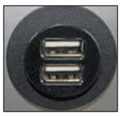 Figure 9-10: USB receptacle
Converter/Inverter
Your motorhome is equipped with a 2800 or 2000 watt Magnum Pure Sine Wave Inverter. When the 120 VAC power is not available, either from the power cord or the generator, the inverter/charger (Figure 9-11) may be used. The control panel for the inverter/charger is located above the driver’s seat. Refer to the manual for your inverter model for more information.

The inverter/charger has two modes of operation:
INVERTER (providing power to your appliances from the batteries), and AC (running from the shore power or a generator). Whenever the inverter is in AC mode, it passes power directly to your appliances as well as recharges the batteries using a 3-stage battery charger (Bulk, Absorption, and Float). This approach to battery charging provides rapid and complete charging cycles without placing undue stress on the batteries. Inverter operation must be enabled on the remote panel.
With search mode enabled, the inverter pulses the AC output looking for an electrical appliance (typically 5 to 100 watts, depending upon the setting you have selected). Whenever there is no load detected, the inverter automatically goes into search mode (sleep) to minimize energy consumption. During this time, the inverter’s green LED flashes (fast) to indicate SEARCH mode. When an appliance is switched on inside the coach, the inverter recognizes the need for power and automatically starts the inverter. Whenever AC Shore Power is no longer sensed, the inverter automatically transfers to battery power with no interruption to your appliances. The inverter’s green LED flashes once every 2 seconds (medium flash) to indicate it is running on battery power and providing AC to the coach.
Whenever AC Shore Power is sensed, the inverter automatically transfers to the shore power with minimal interruption to your appliances. Whenever the inverter is running on nominal AC shore power, it charges the batteries. The inverter’s green LED stays ON (solid) to indicate the first stage of charging. During bulk charging, the charger supplies the maximum amount of constant current to the batteries. As the battery voltage rises to a set value, the charger will then switch to the next charging mode.
As the inverter continues to run on nominal AC Shore Power, and the batteries have been successfully bulk charged, the charger enters its second stage of charging. The inverter’s green LED flashes once every second (fast flash) to indicate absorption charging for 1-3 hours depending upon battery bank selection. The charger then switches to its final mode. As AC shore power continues the inverter’s green LED flashes once every 8 seconds (slow flash) to indicate the third and final stage of charging. The batteries are held at the float voltage as long as AC is present at the inverter’s input. Float charging reduces battery gassing, minimizes watering requirements (for flooded batteries), and ensures the batteries are maintained at optimum capacity.
The inverter monitors the AC Shore Power, the batteries and itself. Whenever a condition occurs that is outside the normal operating parameters, the inverter will take the necessary steps to protect your appliances, batteries, or itself from damage. Whenever the battery voltage reaches a low level, the inverter will initiate Low Battery Cut-Off (LBCO), which automatically shuts the inverter down, along with all connected loads, to protect the batteries from over-discharge damage. The inverter’s LED turns OFF to indicate the fault condition. Refer to the manual for your inverter model for more information.
As the inverter is charging, it constantly monitors the batteries. In the event the battery voltage approaches too high of level, it automatically turns off the battery charger to protect the batteries from damage. The inverter’s LED turns OFF to indicate the fault condition.
| NOTE: High battery voltage might be caused by excessive voltage from the alternator, solar panels, or other external charging sources. |
During inverter and AC Shore Power operation, the inverter monitors the AC and DC circuits. In the event of a short-circuit or overload condition, the inverter will shut down. The inverter’s LED turns OFF to indicate the fault condition. During inverter operation, if the inverter becomes overheated, it will shut down to protect itself from damage. The inverter’s LED turns OFF to indicate the fault condition. For further reading and additional information on the above, please reference your inverter/charger manual that will be found in your Owner’s Information Package.
120 Volt (VAC) AC Receptacles
Your motorhome is equipped with several 120 VAC receptacles (Figure 9-12) located throughout the interior of the motorhome.
These 120 VAC receptacles are of the “three-prong” variety; the third prong being a grounding pin that provides adequate grounding to protect one from any electrical shock.
 Figure 9-12: 120 VAC receptacle
For these receptacles to work properly, do not use an adapter, cheater, or extension cord, which defeats the function of the grounding pin. For the same reason, never remove or bend away the ground prong or pin from any threeprong AC plug so that it would fit a two-prong AC receptacle (i.e., an ungrounded AC receptacle).
Never operate the motorhome if there is an electrical short present, as an electrical short might deliver an electrical shock to anyone coming in contact with the exterior of the unit.
If you feel even the slightest of electrical shock, immediately disconnect the unit from the 120 VAC power source and locate the electrical fault (i.e., typically, it is a break in the grounding circuit).
Do not reconnect the 120 VAC power until after the electrical fault is fixed—the grounding circuit must be continuous from the frame to the distribution panel, to the power cord, and to the earth ground so that electrical-shock protection is realized.
Ground-Fault-Circuit-Interrupt Receptacles
In the kitchen and bath areas, there are 120 VAC GFCI receptacles (Figure 9-13), which provide greater protection against inadvertent electrical shocks.

These specialized GFCI receptacles provide both overload and short-circuit protection for the user. The electrical receptacles located in the slide-out are wired through the kitchen GFCI. The exterior receptacles are wired through the bathroom GFCI. Consequently, if an appliance plugged into a slide-out or exterior receptacle is not working, check for a tripped GFCI in the kitchen or bathroom.
All GFCI-protected receptacles are marked as such, but only one of them might have two pushbuttons on the receptacle (as shown in the picture). The upper pushbutton is a “test” button, which can be used to ensure that the GFCI function is working.
To reset this GFCI breaker, push the lower button (the “reset” button) to restore power to all the GDCI receptacles on this circuit.
These receptacles protect the user from ground faults between an electrically “hot” wire and ground. The GFCI will not reduce the shock hazard if the short is between a neutral and “hot” wire, or two “hotload” wires.
The GFCI must be tested at least once a month. The 120 VAC electrical system must be ON for the GFCI to be tested.
To test the GFCI, the reset button must be pushed in fully before starting the test. Push the test button; this will cause the reset button to pop out, which means that the protected circuits have been disconnected. Push the reset button back in until a “click” is heard—this will reactivate the protected circuit. If the GFCI is working properly, the reset button will remain in the “in” position.
Electrical Generator
The Phaeton uses a 10.0 KW electrical generator (Figure 9-14), which is conveniently located by opening the front hood of the motorhome.

Before starting or stopping the generator, make sure that all the 120 VAC appliances are turned OFF.
After the generator has been started, wait until the transfer switch has connected before turning ON any of the appliances.
The generator can be started from either the remote-start switch located on the dash or directly at the generator itself. The hour meter installed on the generator records the number of hours of operation of the generator motor—this elapsed time is needed for observing necessary maintenance schedules on the generator.
Energy Management System
The energy management system (EMS) (Figure 9-15) distributes all the 120 VAC power throughout the motorhome, whether it comes from the shore power, the generator, or the inverter. The EMS monitors the incoming power, and manages the power to reduce circuit breaker tripping. It does this by briefly shedding power to the loads under its control when the user turns on other more critical appliances in the motorhome. EMS restores power when the appliance is turned off. The EMS panel displays the status of incoming power and the controlled loads.

When coupled with an inverter, EMS reduces battery charge rate before shedding any loads. Working together, an inverter assist feature is available. Normally the inverter is at rest when shore power is available. EMS utilizes the inverter and the coach battery bank to smooth out peak load demands. The inverter assist feature scales back the charge rate in order to have more 120 VAC power available for the appliances.
Electrical Power Cord Reel
In order to pull the power cord off the power cord reel (Figure 9-16), push and release the retract switch, wait 2 seconds and the clutch will release. You now freely pull the power cord. To retract the power cord, hold the switch until the cord is fully retracted.

Automatic Transfer Switch
The automatic transfer box switches 120V AC power from the shore or generator to the coach’s main distribution panel. The transfer box has a delay of around three seconds before switching power to the shore, and a delay of around 30 seconds before switching power to the generator.
If the unit is plugged into the shore but there is no power to the coach, then make sure the shore outlet has power. If power is present, this might indicate that the unit is sensing an open neutral condition. Start the generator; if the power is restored, then the shore plug or the outlet might be defective (the neutral line might be broken).
If there is no power to the coach from the shore or generator, then check the generator circuit breaker. If the circuit breakers are not tripped in the generator or the coach, the transfer box might need to be replaced. For more detailed information on the automatic transfer switch, refer to the specific owner’s instructions found in the owner’s information package.

Circuit Breakers
The 12 VDC circuit breakers (Figure 9-17) are located in an external storage compartment.

When the circuit breakers are shut down or electrically tripped, they must be manually reset by using the main touch panel. These breakers protect various electrical components throughout the motorhome. As needed, manually reset the circuit breaker or breakers as shown in the accompanying figure. When the breaker is tripped, it will be extended outward. To reset it, push the button back in.
Be careful when working around these connections as an accidental electrical short to ground (i.e., momentarily connecting the “positive” or “hot” terminal to any part of the chassis) can be hazardous and harmful.
Some of the electrical circuitry within the motorhome is protected by various fusing systems.
The electrical circuits protected by the fuse block include: headlights, panel light for dashboard, tail lights, optional jacks, turn signals, cruise control, engine computer, accessory fuses, heater and dash air conditioning. Additionally, there is another chassis fuse panel which works in conjunction with the chassis fuse panel and provides comparable protection for the above-listed circuits.
Seven-Pin Towing Connector

Your motorhome is equipped with a standard, pin connector near the towing hitch at the rear of motorhome to supply the necessary circuitry to control a towed vehicle.
The wiring of that connector is shown in the accompanying diagram (Figure 9-18).
Make sure that any cable from the vehicle to be towed is wired correctly to mate properly with the connections shown in the connector. If in doubt about proper wiring, have a qualified service technician prepare and install the necessary cable to mate with the 7-pin connector on the motorhome to ensure proper operation subsequently when any vehicle is actually towed by the motorhome.
When the towed vehicle is uncoupled from the motorhome and the cable is disconnected from the 7 pin connector, be sure to close the spring-hinged cover plate on the connector to protect the contact pins from dirt or debris. In a similar manner, protect the cable end from weather, or debris. One method could be to place the connector end in a heavy-gauge plastic bag (e.g., polypropylene, polyethylene, etc.), secure the bag tightly around the cable with a stout elastic band or tape, and then mount the secured cable in a manner to keep it both from mechanical damage and water intrusion.
When the towed vehicle is again coupled to the motorhome through the towing hitch and the cable is again connected to the 7-pin connector, make sure the resultant connection is tight and solid so that the connection does not jar loose during use. Several supplemental methods to secure that connection have been used; some of which include securing the connection with a strong rubber band or with Velcro-type fasteners to provide a supplemental mechanical backup to the actual electromechanical connection. If a conversion adapter to convert the round, 7-pin connector to a flat, 4-pin connector is needed, purchase one from any RV after-market store.