AHE-250-DO2 Installation Manual
Installing the 250-D02
Install the Aqua-Hot in a compartment which protects the unit and allows service access to the top and front panel of the Aqua-Hot. The Aqua-Hot must be installed in a compartment that is completely closed off from living quarters and accessible only from the exterior.
- Reference the following illustrations below for mounting information.
- Cut out the required mounting flange opening Reference Figure 5.
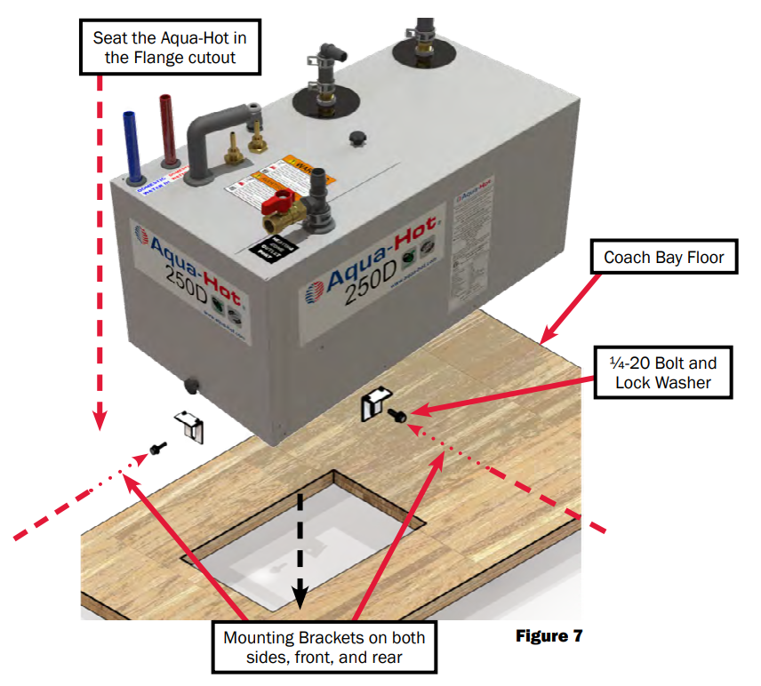
- Install the flange located on the bottom of the Aqua-Hot into the cutout opening. Reference Figure 7 & 8.
- Take the angle brackets and included ¼-20 bolts and washers. Install the angle brackets into the nuts located on the flanges.
- Front view Aqua-Hot dimensions Figure 4.
- Floor cutout information Figure 5.
- ID Label noting the front and service access clearance requirements Page 4.
| Note: Inspect the area beneath the mounting location to ensure that no structural members will interfere with the cutout for the mounting flange. Verify that a support structure of adequate strength has been constructed. Figure 6. |

Support and Clearance


Fluid Expansion Bottle
Installation of the Expansion Bottle
Introduction:
- The fluid expansion bottle is integral to the operation of the Aqua-Hot. It provides an area for hot, expanded fluid to empty into, and also protects the Aqua-Hot from low-fluid, which could lead to catastrophic damage of the Aqua-Hot. Follow the directions in this section to correctly install the fluid expansion bottle.
Installation Procedure:
- Select a mounting location that allows for easy access and clear visibility whenever the storage bay containing the expansion bottle is open.
- Mount the expansion tank as illustrated in Figure 10.
- Connect and clamp the overflow tubing from the expansion tank to the Aqua-Hot’s expansion tank connection.
- Drill a hole in the bay floor and cut a piece of overflow tubing (included with unit) of adequate length so that it can be connected to the top of the expansion tank and extend through the bay floor. The expansion hose should vent to the exterior of the Aqua-Hot bay.
- Locate the wires of the expansion bottle and connect them to wires J43 and J44 on the wiring harness.
- Once complete, secure these wire leads to minimize risk of accidental damage.
| Note: Avoid any bends or dips in the overflow tubing from the Aqua-Hot. Air can become trapped in these bends and will prevent excess antifreeze and water heating solution from depositing properly in the expansion bottle. |


Heat Exchanger Layout

Installation Requirements
Cozy heat exchangers can be mounted in one of two configurations: either flat on the ground, or vertically. Reference Figure 12.
- Supply ventilation cross-sectional area of at least 29in² (74cm²) must be supplied to each heat exchanger.
- Do not supply heat exchangers air which is drawn from the bay areas.
- Return air should be drawn from the same room the heat exchanger is heating.
- The anti-freeze and water heating solution must flow in through the bottom of the heat exchanger, and out the top (reference Figure 24).


Mounting the Heat Exchangers
- Cut out a 2.5” x 10” (7cm x 26cm) opening for each heat exchanger outlet and cold-air return grate as shown in Figure 15.
- Mount each heat exchanger permanently into place. There are 4 tabs on both sides - see Figure 24.
- Install the hot-air outlet and cold-air return grate. Figure 15.
A minimum of supply ventilation cross-sectional area of at least 29in2 (74cm2) must be supplied to each heat exchanger. Please note that a return-air register may not be required, however, adequate return air must be provided to the heat exchanger or you may experience diminished performance of the heat exchanger unit. If the toe-kick area is inadequate to house a heat exchanger for regular installation, a plenum assembly may be purchased to redirect air via ducting. The plenum allows only the desired outlets to be opened by removing the metal insert on the vent. Refer to Figure 14 & 16.
 |
1. Hot Air Outlet Vent |
| 2. Air Ducting Hose | |
| 3. Plenum | |
| 4. Cozy Heat Exchanger | |
| 5. Toe Kick Board |


Heat Exchanger Locations and Clearances
| Note: For single slide-out configurations, it is usually simplest to place a heat exchanger on the opposite side of the coach pointing towards the slide-out. |
- Position the heat exchangers so that even heat is distributed throughout the coach interior.
- The first heat exchanger on the loop will output the most interior heat.
- It is best practice to place the heat exchanger in an area where it can be easily accessed for maintenance.
- Place the heat exchangers as close to the floor as possible for best performance.
- If a heat exchanger is kept in the fresh water storage bay, then the last heat exchanger in the coolant loop should be used.
- The heating air supply may be fresh or recirculated air that is drawn from a clean area not likely to be contaminated.

Boost Pump
If desired, a 6th Cozy Heat Exchanger may be added to the heating loop within your coach. Please note, however, that an additional boost pump is required to provide adequate fluid pressure to allow the 6th heat exchanger to operate as intended.

Wiring the Heat Exchangers
This section will explain in detail how to wire the heat exchangers for optimal functionality. Do not deviate from these guidelines. If a deviation is required, contact Aqua-Hot Heating Systems prior to installing these exchangers for express permission to proceed with modifications.
- Wire each heat exchanger (in a thermostatic zone) in parallel to one another as shown in Figure 22.
- Wire each heat exchanger independently to the J7 plug of the unit controller.
- Pin-out information is shown to the right.
| Note: Quiet-mode functionality of the new controller requires that the heat exchangers be wired directly into the controller. |
| Thermostatic Zone Number | Supply (+) Pin Number | Ground (-) Pin Number |
| 1 | J7-1 | J7-4 |
| 2 | J7-2 | J7-5 |
| 3 | J7-3 | J7-6 |
| Connector Part Numbers | ||
| Part Number | Manufacturer | Description |
| 1-480706-0 | TE Connectivity | J7 Plug Housing |
| 350550-1 | TE Connectivity | J7 Socket Terminal |


Heat Exchanger Install
Plumbing the Heating Zone
The following guidelines should be used when planning the coolant loop for the heating zone. The order of the heat exchangers should consider priority on the loop. Failure to adhere to these installation principles can hinder the operation of the heat exchangers.
- All plumbing should be installed as flatly as possible.
- Extreme rises in height should be avoided to avoid any potential air traps.
- Use ⅝” ID plumbing lines, ¾” SAE J20 type coolant hose, heater hose, or PEX tubing for the single heating loop.
- Use wide-sweeping elbows or “bend supports” whenever the plumbing lines may be susceptible to kinking.
- When exceeding 5 heat exchangers, a boost pump must be installed in the coolant line to provide adequate pressure to ensure that coolant is distributed throughout the heating loop. See Figure 19.
- Plumbing lines should be run in areas where there is no reasonable possibility that they can be pinched off or damaged under normal operating conditions.
- Secure all lines where necessary and apply protective shielding in areas where chafing may occur.
- Rubber coated/closed-type clamps are recommended when securing the plumbing lines.
- Inlet and outlet plumbing lines can be installed with a straight fitting or an elbow.
Instructions:
- Layout the plumbing lines for all heat exchangers (see the example in Figure 25).
- Label each line and designate as an outlet or an inlet line.
- Connect and clamp the outlet line from the heater to the lowest port (inlet port).
- Connect and clamp a line from the first heat exchanger’s highest port, and connect the other end to the next heat exchanger’s lowest point.
- Connect each additional heat exchanger in the same arrangement.
- Connect and clamp the inlet line from the heater to the highest port on the last heat exchanger to complete the heating loop.


| Note: The diagram below is simply a reference to show the layout and flow of the plumbing to and from heat exchangers. Placement and quantity may vary depending on the coach. |


Domestic Water System
Domestic Water System Requirements
- Reference A119.2/NFPA 501C Standard on Recreational Vehicles 1993 Edition for relevant regulatory information regarding the design of Domestic Water Systems.
- The Aqua-Hot is equipped with a pressure relief valve and a tempering valve in order to provide safe hot water without chance of scalding or an over-pressurized system.
- Plumb the domestic water system according to Figure 28.
Plumbing the Domestic Water System
The Aqua-Hot is also able to provide domestic hot water while the boiler tank is up at operating temperature. Activate the diesel burner to provide adequate heat for hot water needs. The electric element will only provide light duty hot water.
The tempering valve is integrated into the cabinet of the Aqua-Hot, and is set upon departure from the Aqua-Hot factory. So long as the tempering valve is not modified, it will provide hot, non-scalding water.
Instructions
- Locate the domestic cold water inlet (blue PEX tube) and connect it to the vehicle’s domestic cold water system.
- Locate the domestic hot water outlet (red PEX tube) and connect it to the vehicle’s domestic hot water system.
| Note: Extended exposure to household bleach will corrode the components of the Aqua-Hot that will potentially dramatically shorten the operational lifetime of the AquaHot. Under no circumstances is the Aqua-Hot to be exposed to household bleach for extended periods of time. This type of damage is not covered by the Aqua-Hot warranty. |

Diesel Fuel System
The following section will outline details of installing the diesel fuel delivery system to the Aqua-Hot 250-D03. These guidelines and instructions are to be followed exactly. Failure to follow instructions herein can cause damage to the AquaHot unit, coach, and may cause serious personal injury. Please note that the fuel ports on a D03 product are reversed from the previous D01 products - see Figure 33.
Fuel Filter
A 10 Micron diesel fuel filter must be installed at the diesel fuel source at all times during the operation of the Aqua-Hot 250-D03. This fuel filter ensures clean fuel is delivered to the fuel nozzle at all times. Ensure that the fuel filter assembly is mounted in an accessible area, as the fuel filter needs to be replaced regularly to ensure optimal operation of the 250-D03.
| Note: If an auxiliary fuel tank is required, be sure to consult the ANSI/NFPA 1192 Handbook concerning heating systems’ diesel fuel specifications, and fuel distribution specifications. |
| Note: Ensure that the fuel filter is installed with correct flow in mind as referenced in Figure 34. |

Fuel System Requirements
- The diesel fuel supply should be drawn directly from the vehicle’s main fuel tank, if applicable.
- The fuel tank should be equipped with a dedicated fuel pick-up pipe (outlet port and inlet port).
- Use ¼” I.D. (Inside Diameter) fuel lines.
- The combined length of the supply and return fuel lines should not exceed 50 feet in total length.
- All fuel lines should be laid as flat as possible, and any extreme rises in height should be avoided to eliminate any potential air traps.
- Run the fuel lines in areas where they cannot be pinched, kinked, or otherwise damaged during normal operation.
- Run the fuel tank outlet fuel line past the fuel filter in preparation for Step 5.
- Secure all fuel lines where necessary, and apply protective shielding in areas where chafing may occur.
- All fuel-fitting hardware (at the vehicle fuel tank, fuel filter, and Aqua-Hot parts) must be ¼” NPT or greater with a barbed fitting. Fuel fittings that are less than ¼” NPT may restrict fuel flow, thereby compromising the diesel burner’s performance.
- The maximum allowable suction height is 7 feet. Reference Figure 36.
- The maximum allowable head pressure is 10 feet. Reference Figure 37.
Fuel System Installation
- Run two ¼” fuel lines from the fuel tank inlet and outlet ports to the Aqua-Hot. Label both fuel lines indicating whether the line is incoming or outgoing.
- Install and tighten the fuel fittings onto the two ports of the fuel filter. Reference Figure 34 for the correct connection configuration.
- Install and tighten the appropriate fuel fittings onto the Aqua-Hot’s fuel ports.
- Connect the Aqua-Hot’s fuel lines to the fuel tank.
- Cut the fuel line at the fuel filter mounting location and connect the fuel lines as illustrated in Figure 34.


Exhaust System
This section outlines in detail the specifications and requirements for installing the exhaust system. These requirements must be adhered to in order to create optimal operating conditions for the Aqua-Hot unit.
Exhaust System Requirements
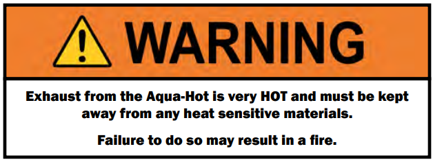
- Do NOT direct exhaust downward as fire may result when parked in dry, grassy areas.
- Exhaust must not terminate beneath the vehicle, or beneath an openable window or vent.
- Do NOT terminate the exhaust pipe within the awning area of the coach, if applicable.
- Ensure that the exhaust is shunted away from slide-out areas.
- Angle the exhaust pipe away from, and towards the back of the vehicle so that the exhaust naturally moves away while the vehicle is in motion.
- Use standard 2” automotive exhaust pipe and avoid any bends, if possible.
- Do NOT use galvanized pipe or fittings, only black-iron pipe fittings are permitted for use.

Refer to “Internal Combustion Engine Exhaust and Vehicle Wall Openings”in RVIA’s ANSI/NFPA 1192 Handbook for Recreational Vehicle Standards, as well as the National Fire Protection Association’s (NFPA) 1192 Standard on Recreational Vehicles for additional information.

Should the particular application require modification of the exhaust pipe, please contact the Aqua-Hot Heating Systems Product Application Department at 574-AIR-XCEL (574-247- 9235).
Installing the Exhaust System
Aqua-Hot separately supplies a kit that contains two 1.5” NPT black pipe nipples - one is 3” in length, the other is 4” in length. These three exhaust system components must be utilized with all Aqua-Hot product installations. Be sure to reference Figures 40 & 41 to determine which exhaust nipple should be connected directly to the Aqua-Hot’s exhaust port (i.e. the 3” or 4” black pipe nipple).
- Run the exhaust pipe to the driver’s side or the back of the vehicle to ensure that the exhaust fumes cannot enter into the passenger compartment. Be sure to keep the exhaust away from the slide-out areas.
- Be sure to secure the end of the exhaust pipe to the vehicle with the proper exhaust hanger/support hardware.


Wiring the Aqua-Hot
This section will introduce the basic considerations, practices, and information necessary to wire the Aqua-Hot to any relevant coach-side systems.

J7 Plug:
The J7 plug is responsible for managing all zone fan power connections, and boost pump supply and return.

| Manufacturer | Part No. | Common Name |
| TE Connectivity | 1-480706-0 | 9-Position Mate-N-Lock |
| TE Connectivity | 350550-1 | Mate-N-Lock Power Contacts |
Once all the required hardware has been acquired, wire the J7 plug according to the table below. J7-9 is not used.
| Pin Number | Function | Connect To |
| J7-1 | Fan 1 Supply | Zone 1 Fans (+) |
| J7-2 | Fan 2 Supply | Zone 2 Fans (+) |
| J7-3 | Fan 3 Supply | Zone 3 Fans (+) |
| J7-4 | Fan 1 Ground | Zone 1 Fans (-) |
| J7-5 | Fan 2 Ground | Zone 2 Fans (-) |
| J7-6 | Fan 3 Ground | Zone 3 Fans (-) |
| J7-7 | Boost Pump Supply | Boost Pump + |
| J7-8 | Boost Pump Ground | Boost Pump - |
| J7-9 | UNUSED | UNUSED |
J8 Plug:
The J8 plug is meant to handle the zone thermostats and House Power Sense functionality. House power sense functionality will be described in detail later in this manual.

| Manufacturer | Part No. | Common Name |
| TE Connectivity | 1-480710-0 | 15 Position Mate-N-Lock |
| TE Connectivity | 350550-1 | Mate-N-Lock Power Contacts |
Once the required hardware has been acquired, wire the J8 plug according to the table below. Pins J8-10 through J8-15 are not utilized.
| Pin Number | Function | Connect To |
| J8-1 | Zone 1 Thermostat In | Zone 1 Thermostat |
| J8-2 | Zone 1 Thermostat Supply | Zone 1 Thermostat |
| J8-3 | UNUSED | UNUSED |
| J8-4 | Zone 2 Thermostat In | Zone 2 Thermostat |
| J8-5 | Zone 2 Thermostat Supply | Zone 2 Thermostat |
| J8-6 | UNUSED | UNUSED |
| J8-7 | Zone 3 Thermostat In | Zone 3 Thermostat |
| J8-8 | Zone 3 Thermostat Supply | Zone 3 Thermostat |
| J8-9 | House Power Sense | 12V DC Power (+) |
| J8-0 | UNUSED | UNUSED |
| J8-11 | UNUSED | UNUSED |
| J8-12 | UNUSED | UNUSED |
| J8-13 | UNUSED | UNUSED |
| J8-14 | UNUSED | UNUSED |
| J8-15 | UNUSED | UNUSED |
J3 Plug:
The J3 plug connects to the on-board RVC system of the coach. It is a 4-pin connector with self contained power pins. See the diagram below for the crimping information for the J3 plug. Crimp these parts together using pliers.

| Manufacture | Part No. | Description |
| 3M | 37401-2165-000 FL 100 | 4-Position MALE Plug |
| 3M | 37104-2165-000 FL 100 | 4-Position FEMALE Receptacle |
| General Cable | E2104S.41.02 | 4COND 22AWG WHT SHLD Cable |
The parts listed above can be purchased from any major electronics retailer. Only the parts listed above are approved for use in the Aqua-Hot.
| Pin Number | Description |
| J3-1 | 12V DC Power |
| J3-2 | Data |
| J3-3 | Data |
| J3-4 | Ground |
| Note: For networked control of the Aqua-Hot Controller, Aqua-Hot requires system integrators ensure that individual commands are received and processed. Aqua-Hot requires that commands be repeated or confirmed so that if a single message were dropped, or if there is a brief network disturbance, the Controller would get into the correct state as soon as the disruption was removed. The Aqua-Hot Controller monitors the heating system and handles all logic relating to safeties and heating control. As such, the system integrator is required to display all pertinent status information but not use that information to lock out operation or add additional safety layers that could impact the end of operation if a message from the Controller was missed. |

Connecting the 250D to 12V DC Power

The section will outline the requirements, steps, and information necessary to connect the Aqua-Hot to the vehicle’s 12V DC power system. Follow all guidelines and pay attention to all notes contained herein. Failure to adhere to these guidelines can inhibit unit performance, and may cause damage to the Aqua-Hot and/or the coach.
- Installation must be performed by a qualified, professional according to current national regulations. Reference A119.2/NFPA 501C Standard on Recreational Vehicles 1993 Edition for relevant national regulatory information.
- Select the correct wire gauge for installation referencing ANSI/RVIA-LV.
- Protect the Aqua-Hot from over-current and shorting by incorporating a 20A breaker (minimum) to the Aqua-Hot’s coach-side power connection.
- Acquire the relevant parts for connecting the Aqua-Hot to 12V DC power by referencing the table below.
| Deutsche | Amphenol | |
| Pins | 1060-12-0222 | AT60-12-0222 |
| Housing | DPT04-2P | ATP04-2P |
| Wedge | WP-2P | AWP-2P |
- After crimping and assembling the power connector, connect this plug to its receptacle on the Aqua-Hot until it clicks into place.

- The image above is simply a reference. A professional, licensed installer needs to determine the necessary components and configuration according to local codes and standards.
- The 12-volt supply to the heater must be routed directly from the battery.
- All power circuits must be protected with fuses or automatic circuit breakers.

Connecting the Aqua-Hot to AC Power

The following section explains in detail how to wire and connect the Aqua-Hot into your coach-side 120V AC power system. Included are examples of plugs and connections, as well as mating part numbers and location call-outs.
The Aqua-Hot utilizes Molex 19403 and 19045 series connectors for the AC electrical circuit. These are self-contained connectors which can be readily purchased from your choice of electronics supplier. Listed below are three different mating connections.
- Installation must be performed by a qualified professional according to current national regulations. Reference A119.2/NFPA 501C Standard on Recreational Vehicles 1993 Edition.
- The boiler must be connected to a 120V AC supply permanently and be protected with a 20A breaker (minimum). The 120V AC must be separate from 12V DC.
- It must be possible to disconnect the power to the boiler, either an easily accessible plug or a circuit breaker.

- Route three 120V AC power source wires to the Aqua-Hot heater.
- Using one of the Molex connectors described below, crimp the 120V AC power source wire into the connector.
- Plug the new crimped 120V AC Molex connection into the mating Molex connection on the Aqua-Hot.
| Self-Contained Power Connector - 2 Circuit for Solid Wire | ||
| Size | Part Number | Housing Color |
| 12AWG-14AWG | 19045-1000 | White |
| Self-Contained Power Connector - 2 Circuit for Stranded Wire | ||
| 14AWG-16AWG | 19403-1011 | Blue |
| 12AWG | 19403-1010 | Yellow |

Filling the Aqua-Hot
Filling and Purging the Aqua-Hot 250-D03: Before the first activation of the Aqua-Hot, fill the unit with antifreeze and water heating solution. Without the solution present, the Aqua-Hot will not operate. Follow the directions below to fill and purge the Aqua-Hot.
A 50/50 mixture of “GRAS” (Generally Recognized as Safe) approved propylene glycol antifreeze and distilled or deionized water is recommended. The mixture may be modified to provide the most adequate freezing, boiling, and rust/ anti-corrosive protection. Reference pages 40-41 for more information about antifreeze.
Procedure:
- Locate the fill valve at the zone port outlet (Figure 57).
- Make a ½” NPT connection from the propylene glycol source to the fill valve.
- Remove the access cover and locate the 3-way valve in the Aqua-Hot. Ensure that the sight glass is oriented as shown below. Reference Page 5, Figure 2 (Item #4) for the 3-Way Valve location.

| Note: If the sight glass is not oriented in this way while the unit is cold, apply power to the main harness connection and the valve will return to horizontal. |
- Activate the fluid transfer pump and begin filling the AquaHot through the fill valve.
- When the fluid level reaches the cold mark on the expansion bottle, deactivate the fluid pump.
- Close the fill valve and disconnect the pump.
- Reattach the access cover.
- Turn on the burner at the interior control panel and set the thermostat to its maximum temperature to allow for interior heating. Let the Aqua-Hot run for at least 20 minutes to ensure that any air in the heating loop has been purged. If necessary, top off the propylene glycol solution at the fluid expansion bottle.


Aqua-Hot First Operation
Activation Instructions (Electric Element):
- Make sure power supply to the Aqua-Hot is on.
- Confirm that the antifreeze and distilled water heating solution is adequately filled.
- Confirm the system and heating loop has been properly purged of any air.
- Make sure to flush the domestic water system thoroughly with clean water prior to use.
- Tap the electric element to “ON” on the Aqua-Hot LCD screen, or the coach control panel, to supply the 120V AC electric element with power.

- Allow approximately 20 minutes for the electric element to heat the tank. Turn on a hot water faucet, and allow to run until hot water flows. Once there is hot water, close the faucet. This will verify that the electric element is operating as it should.
Once these checks have been confirmed, the electric heating element is now ready for normal operation and use.

The first operation of the burner with the Aqua-Hot may not light up perfectly. This is normal and may take a couple tries to get the fuel lines purged of air before a successful start-up.
Activation Instructions (Diesel Burner)
- Make sure there are no blockages or debris to the exhaust outlet or combustion air inlet.
- Make sure the plumbing lines and fuel lines are properly purged and free of air.
- Make sure there is adequate fuel in the vehicle fuel tank (at the least ¼ tank).
- Turn on the burner on the heater control panel.

- Once the burner turns on, the circulation pump and combustion air fan should run (can be determined by listening).
- The burner should start up after approximately 120 seconds. This can be determined by the hot exhaust exiting from the exhaust tube.
- Allow the burner to run a full cycle. Turn on the heat or hot water inside the RV to confirm the burner is properly operating.
| Note: It is recommended to run the burner for at least 20 minutes every month to ensure optimum heater condition. |
Once these checks have been confirmed, the diesel burner is now ready for normal operation and use.
Winterizing the Aqua-Hot
The Aqua-Hot’s domestic water heating system must be completely drained of domestic water at any time the heater is stored where freezing temperatures may be experienced. Please follow these instructions when winterizing the AquaHot domestic water heating system. Reference Figure 60 for a system overview.
| Note: The Aqua-Hot can continue to be used for interior heat once the domestic hot water system has been winterized. |
- Disconnect or shut off any external sources of freshwater.
- Open all faucets, shower heads, and similar. Open both the “HOT” and “COLD” valves on the faucet, if applicable.
- If only one valve, open it to the “halfway point”.
- Ensure that the coach is connected to a waste collection point, such as a grey water tank.
- Attach an external fluid pump to your fresh water connection.
- Ensure that the fill pump intake hose is situated in a large enough supply of “GRAS” winterization antifreeze so that the pump does not run dry if left unattended.
- Activate the external fill pump. Allow the pump to run until ONLY antifreeze is exiting the faucets in the coach.
- Once this has been completed, deactivate and disconnect the external fluid pump.
- Close all but one faucet in the coach. This will allow the winterization antifreeze to expand and contract as necessary with temperature changes, thereby greatly reducing the likelihood of pressure-related damage to interior pipes.

De-Winterization:
- To de-winterize the unit, connect a freshwater source to the coach.
- Ensure that all the interior faucets have been re-opened.
- Turn on the external water source, and allow it to run until winterization antifreeze no longer flows from any faucets.

System Schematics


