Aqua-Hot: 125-D02 Installation Manual
Access the complete PDF here: AHM-125-D02-Installation-Manual
Caution Notes
As you read this information, take particular note of the NOTICE, CAUTION, WARNING, and DANGER symbols when they appear. This information is important for safe and efficient use of the Aqua-Hot system. NOTICE signals a situation where potential damage to the Aqua-Hot could occur.
NOTICE signals a situation where potential damage to the Aqua-Hot could occur.

CAUTION signals a situation where potential harm or risk of minor or moderate injury could occur if you do not follow instructions.

WARNING signals a hazardous situation where potential harm, risk of serious injury, or death could result if instructions are not followed.

DANGER signals a situation where immediate risk of serious injury or death will result if instructions are not followed.

NOTE: This manual will also use notes sections similar to this one to draw attention to features and practices which must be observed.
Installation Checklist
Introduction
The following table is a checklist of important items that need to be completed for a successful install of the M125D AquaHot heater in your RV. Please confirm each item is properly completed before utilizing the Aqua-Hot heating system. Should additional assistance be needed, please contact the Technical Support team at 574-AIR-XCEL (574-247-9235), Monday through Friday, between 7:00am and 4:00pm MST. You can also email the service department at servicedept@ aquahot.com.

Warning
Read and understand all instructions before installing the Aqua-Hot unit and the external diesel burner. Aqua-Hot Heating Systems is not liable for damage resulting from failing to follow instructions contained in this, and any other Aqua-Hot documentation relevant to this unit.
Improper installation, adjustments, service and maintenance can cause personal injury or loss of life. Reference the installation and user manuals before installation or service.
Contact your authorized service center or Aqua-Hot Heating Systems if you have any questions before starting installation.

Figure 1: Installation Checklist Chart

Introduction
Read all instructions before installing the Aqua-Hot unit and the external diesel burner. Aqua-Hot Heating Systems is not liable for damage resulting from failing to follow instructions contained in this, and any other Aqua-Hot documentation relevant to this unit.
- Read this manual before installing or using the Aqua-Hot System to reduce the risk of injury to persons or damage to the equipment.
- The product identity label contains specifications of the unit, to what standards it has been tested, and important safety notices.
- Disconnect electric wiring to the Aqua-Hot System before welding or plasma cutting the RV to avoid damage to equipment.
- The Aqua-Hot tank and heating loop operate at 7.0 PSI. Maximum testing air pressure to the tank must not exceed 18 PSI. Exceeding this rating will cause internal damage to the Aqua-Hot.
- Use caution when working on or near any propane/diesel fuel system

- DO NOT connect the 12-volt DC power to the Aqua-Hot if the vehicle requires welding.
- At maximum operating temperature, the coolant will be very hot and scalding. Hot vapor or coolant may cause serious burns or injury. Be aware of hot surfaces.
- Use special caution when children are present. Children must not be allowed to play with the heater or perform cleaning and maintenance.
- Installation and repairs may only be carried out by an authorized, factory-trained Aqua-Hot technician. The heating system must be installed in accordance with local codes, or in accordance with the Standard for Recreational Vehicles, (RVIA) ANSI A 119.2/NFPA 501C, NFPA 1192.
- At maximum operating temperature, the hot air outlet will be very hot that may result in serious burns or injury. Be aware of hot surfaces.
- The diesel burner must be installed in a location that is closed off from living quarters and accessible only from the exterior of the vehicle.
- The burner produces very hot temperatures that can ignite surrounding flammable materials. The burner should be turned off when loading or unloading flammable materials
Safety Features
Low-Voltage Shutdown
The Aqua-Hot Controller is designed to operate between 11V DC and 16V DC. If the Controller detects that it is receiving voltage below 11.8V DC, a System Voltage fault will trigger a display on the LCD screen. If the Controller system drops below 11.2V DC for 30 seconds, it will discontinue operation of the Aqua-Hot heating system.
Over-Current
An Over-Current fault condition occurs when too much current is drawn by a component, usually a fan or pump. When this fault is triggered, the output channel is shut off until the system has been reset or power-cycled.
Over-Temperature
An over-temperature fault will occur if your Aqua-Hot heating system has reached 218° F. The Controller will deactivate the heater and display an over-temperature fault on the LCD display screen.
Low-Level Cutoff
If the system senses low fluid levels, the heating system will shut down all fans, heat sources, and pumps until the unit is adequately refilled.

Safety Installation of the Diesel Burner
Be sure to become familiar with the installation process and the documentation before installing in the vehicle.
• Make sure to protect the burner during installation. Do not drop or stand on the burner.
• Avoid abruptly shutting down the burner prior to the purge cycle. The burner fan will continue to run for several minutes after being shut off to cool down and purge unused fuel.
• Only turn off the burner at the control panel in the interior of the vehicle.
• Do not disconnect the 12V DC power supply prior to the purge cycle.
• Only shut down the burner via the battery disconnect in the case of an emergency or danger.
• Do not allow the wiring or wiring harness to come into contact with sharp edges on metal panels. The wires can become damaged and short circuit and potentially cause a fire. Use caution when installing the wiring.
• Protect any vehicle parts near the burner from excessive heat damage, or from contamination from fuel.
• Make sure the internal combustion burner will not pose a fire hazard even in an overheat situation. Take care in placing the burner with enough space from vehicle parts and that the burner will have ample ventilation.
• The serial label must be visible and legible after the burner has been installed.
• All precautions must be taken to minimize the risk of personal injury or damage to the burner or vehicle.
• It must be obvious to the user when the burner is switched on or off.
• The burner may not be mounted in a position above the M125D tank.
Fuel Supply
• Do not use the heater in enclosed spaces such as a garage. The fumes produced from the exhaust can be toxic. Do not use the burner while refueling or while other appliances are being serviced or refueled.
• The fuel filler neck should be installed in a compartment that is closed off from living quarters and must have a tightly fitting cap to prevent any fuel leaks.
• A visible, legible sign must be attached to the filler neck that the burner be turned off before refueling. A similar warning is included in the manufacturer’s operating manual.
• The diesel fuel filter is to be replaced every year for optimal performance.
Exhaust System

• Do not operate the burner in an enclosed space or a space that does not have exhaust ventilation. Fumes from the exhaust may be toxic.
• The exhaust system must be positioned so that the fumes will not get into the interior of the vehicle through ventilation openings or windows.
Combustion Air Inlet
• The burner combustion chamber air must not be taken from the interior of the vehicle, only fresh air from the exterior.
• An intake line is required for the combustion air.
• The air inlet must be positioned in an unobstructed manner.

System Overview
The Aqua-Hot M125D is a Hydronic Heating System that can provide heat and hot water on demand using a built-in electric heating element and an external diesel burner.
The Aqua-Hot Heating is a 2-in-1 System
1. Interior heating system: provides quiet, comfortable interior heat and even temperatures.
2. Tank-less hot water system: provides a flow of comfortable hot water.
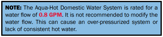
The Aqua-Hot heating system heats an ethylene glycol based antifreeze and distilled water solution that is stored in the AquaHot’s boiler tank. This fluid solution must be up to operating temperature before the Aqua-Hot will provide interior heat or hot water. The tank-less hot water system produces approximately 0.8 GPM of hot water. To get the Aqua-Hot to temperature, turn the electric heating element and/or the external diesel burner to the “ON” position on the Aqua-Hot LCD screen (shown below), or on the RV control panel. It may take up to 20 minutes to get to operating temperature before heat or hot water are available

For continuous hot water or heat in colder conditions, it is recommended to utilize the external diesel burner. The electric heating element will provide heat only in mild conditions and provide light duty hot water needs.
Should additional assistance be needed, please contact the Technical Support at 574-AIR-XCEL (574-247-9235), Monday through Friday, between 7:00am and 4:00pm MST.
Important Notes:
• A qualified installer or service technician must perform equipment installation or service. Contact Aqua-Hot for Factory Authorized Service Centers or Certified Technicians located near you at www.aquahot.com/service-help, or call us at 574-AIR-XCEL (574-247-9235).
• Warranty work must be performed by an Aqua-Hot Authorized Service Center.
• Your on-product identity label contains the specifications of your unit. Factory settings may be adjusted by the vehicle manufacturer, confirm final setting with your dealer.
• This heating system has been certified for installation only in recreational vehicles, not certified for use in boats.
• The Aqua-Hot heating system operates independently of the vehicle engine and is connected directly to the electrical system of the vehicle. The diesel burner is only connected directly to the fuel system and the battery of the vehicle.
• Please read this manual and follow instructions to avoid injuries during installation and/or operation.
Heat Priority Option:
The Aqua-Hot comes equipped with a three-way valve (sometimes known as the summer/winter valve). This controls the flow of the antifreeze and water heating solution within the Aqua-Hot to deliver either hot water or interior heat as priority. Tapping on this element will change the valve’s orientation. When this element is activated, it overrides the automatic function and orients the valve to interior heat. When the element is not activated, the unit is in automatic mode and the valve is automatically oriented based on the Low-Temperature Cut-Off.

System Features


Component Cut-Aways


Interior Components
Installing the Aqua-Hot
Install the Aqua-Hot in a compartment which protects the unit and components, and allows service access to the Aqua-Hot. Make the following considerations when supporting the AquaHot to ensure its most optimal operation and location.
1. Reference the following illustrations below for mounting information.
2. Mock up the locations for the diesel burner and the AquaHot components. Ensure there is adequate room for installation and service.
3. Identify the needed lengths of hose, insulation, wiring, and the proper connectors to reach each component. Reference Figure 11 and the parts list at the back of this manual.


Boiler Tank
Install the Aqua-Hot in a compartment which protects the unit and components, and allows service access to the Aqua-Hot. Make the following considerations when supporting the AquaHot to ensure its most optimal operation and location.
1. Reference the following illustrations below for mounting information.
2. Mock up the locations for the diesel burner and the AquaHot components. Ensure there is adequate room for installation and service.
3. Identify the needed lengths of hose, insulation, wiring, and the proper connectors to reach each component. Reference Figure 11 and the parts list at the back of this manual.
Mounting the Boiler Tank (Figure 11)
1. Install barb adapters into the “Coolant In” and “Coolant Out” ports on the bottom of the tank.
• 90° and straight fittings are supplied in the kit. Choose the appropriate fittings for the application.
• Apply PTFE tape to fitting threads before installation.
2. Using 4 screws, attach the tank to the mounting location. Ensure the tank is level and no wires are pinched during mounting.
3. Using the provided hose clamp, attach the provided 5/16” heater hose to the overflow barb on the filler neck of the boiler tank.
4. Route the overflow hose through a grommeted and sealed hole in the floor of the vehicle to the exterior.
Zone Pump Considerations
• Must be located below the level of the tank in a cabinet or storage to prevent accidental contact with hot surfaces.
• Must be inside the vehicle and provide adequate space to route plumbing lines without kinks or sharp bends.
• It is recommended to use the alternate mounting method where space in the tank cabinet allows. The 90° barb fitting must be installed in the “COOLANT OUT” port when using the alternate mount.
1. Slide the pump mount onto the pump.
• Orient the pump in the pump mount to simplify the plumbing and ensure access to the electrical plug.
2. Screw the pump mount to the mounting location.
Alternate Mounting (Figure 12)
1. Wrap the provided arrowhead push mount zip tie around the pump.
2. Position the arrowhead to align the pump ports in a convenient direction for plumbing and tighten the zip tie.
3. Connect the “Coolant Out” port to the pump with a 4in section of heater hose and two hose clamps.
4. Snap the arrowhead mount into the bracket on the bottom of the tank.
Plate to Plate Heat Exchanger
• Must be mounted on a vertical wall able to withstand sustained temperatures of 180°F.
• Must be located below the level of the tank in a cabinet or compartment to prevent accidental contact with hot surfaces.
• “Glycol Out” and “Water In” ports at the top, “Glycol In” and “Water Out” ports at the bottom.
• Use 4 - #8 Screws or larger.
Mounting (Figure 13)
1. Using 4 screws attach the exchanger to the mounting location. Ensure the exchanger is vertically level.
2. Apply a hot surface warning decal near the mounting location.

Tempering Valve
• Must be in a cabinet or compartment to prevent accidental contact with hot surfaces.
• Mounting surface must be able to withstand sustained temperatures of 180°F.
• In the event of an emergency pressure release, the valve can emit scalding water. Ensure its location will allow the valve to safely do so.
Mounting (Figure 14)
1. Using the provided P-clamps and two screws, attach the valve to its mounting location. It may be helpful to leave the screws loose until the domestic water system is plumbed to the valve.
2. Apply a hot surface warning decal in an unobstructed location near the valve.

Three-Way Valve
• Must be in a cabinet or compartment to prevent accidental contact with hot surfaces.
• Mounting surface able to withstand sustained temperatures of 180°F.
Mounting (Figure 15)
1. The provided P-Clamps use the coolant lines to mount the valve. Choose a location and wait to mount the valve after plumbing the system.
2. Apply a hot surface warning decal in an unobstructed location near the valve.

Aqua-Hot Controller
• Choose a location safe from dust and moisture.
• This component is rated for the heat generated by the other Aqua-Hot components and can be in the same compartment.
• Ensure enough space surrounding the controller to route wiring with sufficient strain relief
Mounting (Figure 16)
1. Using 4 screws, mount the controller in the chosen location.

LCD Screen
• All user inputs will be done at the LCD screen. Choose an easy-to-access location that is safe from damage during normal use of the vehicle.
• A cutout is needed in the mounting surface to provide clearance for the back of the screen and to route the RVC cable. There is a sticker with a template for the cut-out.
Mounting (Figure 17)
1. Remove the bracket from the back of the LCD screen. Note the orientation markings in the corner of the screen and bracket.
2. Cut a hole in the mounting location for the bracket.
3. Using 4 small flat head screws or rivets, attach the bracket to the cabinet. Ensure the bracket is oriented correctly.

K-Line Converter
• Choose a location safe from dust and moisture.
• This component is rated for the heat generated by the other Aqua-Hot components and can be in the same compartment.
• Ensure enough space surrounding to route wiring with sufficient strain relief.
Mounting (Figure 18)
1. Using 4 screws, mount the K-Line Converter.

Heat Exchanger Installation Requirements
• Cozy heat exchangers can be mounted either flat on the ground or vertically, and as close to the floor as possible for best performance, in an area where it can be easily accessed for maintenance. Reference Figure 19.
• Supply ventilation cross-sectional area of at least 29in^2 must be supplied to each heat exchanger.
• Do not supply heat exchangers air that is drawn from the bay areas. Return air should be drawn from the same room the heat exchanger is heating.
• The heating air supply may be fresh or recirculated air that is drawn from a clean area that is not likely to be contaminated with exhaust or other toxins.
• Coolant must flow in through the bottom of the heat exchanger, and out the top (Figure 23).
• The AHM-125D is designed to work with up to 3 thermostatic heating zones and a maximum of 3 Cozy’s. Two Whisper exchangers can be substituted for one Cozy.
• Position the heat exchangers so that even heat is distributed throughout the RV interior. The first heat exchanger on the loop will output the most interior heat.
• If a heat exchanger is kept in the freshwater storage bay, the last heat exchanger in the coolant loop should be used (see Figure 20).
• It is not recommended to place a heat exchanger on the slide-out section of any vehicle due to the high probability of damage occurring to the heating loop from moving parts.


Heat Exchangers
1. Cut out a 2.5” x 10” opening for each heat exchanger outlet and cold-air return grate as shown in Figure 22.

2. Mount each heat exchanger permanently into place. There are 4 tabs on both sides - see Figure 23.

3. Install the hot-air outlet and cold-air return grate. A minimum of supply ventilation cross-sectional area of at least 29in2 (74cm2) must be supplied to each heat exchanger.

Thermistors
• Choose locations that accurately reflect the temperature of the zone.
• Each zone requires one thermistor.
• A thermistor can only operate one zone.
○ Multiple cozy’s can be in the same zone.
• Mounting at eye level, where possible, will provide the most accurate reading.
• Avoid locations that will frequently be in direct sunlight.
• Avoid locations close to windows and doors.
Mounting (Figure 25)
1. Choose a location for the thermistor.
2. Drill the two mount holes and a third hole for the wires. Attach the thermistor using two fasteners.

Mounting the Burner to the Vehicle
Install the external diesel burner in a location separate from the living spaces that protects the unit, and also allows service access to the burner.
• Reference the illustrations below for mounting information.
• The burner is best placed in a location where it can be easily accessed for service and maintenance.
• The burner must not be mounted higher than the tank.
• The bracket must be secured to the vehicle with at least 4 M6 screws.
• Fasten the burner bracket firmly, the 4 corners should be lined with rubber shock absorbers.
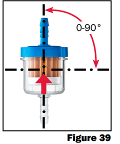
• The burner can be oriented to suit different orientations/ positions, however it should not exceed an angle greater than 90°. The recommended orientation is horizontal with the exhaust pipe vented downwards.
• If mounting to the frame rail, use (4) M6 bolts. Drill (4) M6 holes where the burner will be mounted, and fasten the bracket to the vehicle with (4) M6 nuts.
• Secure the burner to the bracket using appropriate mounting hardware, M6*95 bolt torqued to 6 lb-ft.


Rotating Coolant Fittings
1. Remove the 6 bolts on the coolant fitting retaining plate.
2. Wiggle each fitting while carefully pulling up to release the fittings from the casting.
3. Flip the retaining plate over and locate the star bushing used to align the fittings.
4. Press the fitting from the top of the plate to disengage the star bushing.
5. Rotate the fitting to the correct orientation.
6. Press the star bushing and fitting back into the retaining plate.
7. Replace the retaining plate and fittings onto the burner. Ensure the fittings align with the ports in the burner casting.
8. Wiggle each fitting while pressing them into the casting ports. • Lubricate the O-rings with coolant.
9. Reinstall the 6 bolts attaching the retaining plate to the burner

Mounting
1. Using the 4 provided M6 bolts and M6 nuts, fasten the burner bracket to the mounting location. If different bolts are required, ensure they are M6 or larger.
2. Position the burner onto the bracket making sure the tabs of the bracket engage the grooves on the burner.
3. Align the mount hole on the burner with the threaded hole on the bracket and install the provided M6 x 95mm bolt.

Burner Pump
• Choose a protected location near the burner. The pump wire harness from the burner must be able to reach the pump.
• Position the pump to simplify plumbing to the burner.
Mounting
1. Locate the coolant pump. The pump mount should be attached to the pump.
2. Using the provided self-drilling screw, attach the pump to the mount location.

Combustion Air System
The combustion air should not be supplied from living areas. The air intake opening must not point in the direction of travel. It also should be free from potential clogs from snow, debris, or water.
• Installation of air intake and exhaust system is shown in Figure 35.
• The intake silencer does not act as a filter. Choose a location which limits exposure to dust and moisture. • Limit opportunity for vehicle or burner exhaust to be drawn into the burner.
• The intake must not point in the direction of travel.
• The intake tube must not be longer than what is included.
The combustion air intake may be installed in the same compartment as the vehicle’s fuel tank, but the air intake must come from the exterior. The exhaust must be routed to the exterior and any holes must be splash-proof.

Mounting (Figure 34-35)
1. Using the provided hose clamps, attach the open end of the intake tube to the intake port on the bottom of the burner.
2. On the other end of the tube, remove the metal cap.
3. Cut the fitting on the silencer to the appropriate size for the intake tube.
4. Thread the silencer into the intake tube.
5. Using the provided silencer mount bracket, mount the silencer to the chosen location.
6. Secure the intake tube where convenient to prevent rubbing and abrasion.


Exhaust System

The specifications and requirements must be followed carefully. Failure to follow instructions may result in improper and unsafe operation of the M125D and burner. Please comply with all applicable legal requirements.
• Reference the diagram in Figure 35.
• The exhaust can reach upward of 500°F.
• Ensure there is no contact with temperature sensitive parts. Leave at least a 1” air buffer between the exhaust and any parts of the vehicle.
• Never terminate under the vehicle, a window, or any vents.
• Never extend more than ⅜” past the vehicle’s body.
• Never add more than 270° of cumulative bends.
• The total exhaust length must not exceed 3’ - 9”.
• Never point the exhaust straight down or close to the ground.
• Ensure the muffler drain hole is pointing down.
Refer to the “Internal Combustion Engine Exhaust and Vehicle Wall Openings” in RVIA’s ANSI/NFPA 1192 Handbook for Recreational Vehicle Standards, as well as the National Fire Protection Association’s (NFPA) 1192 Standard on Recreational Vehicles for relevant information.

Instructions
1. Plan where the muffler will be located.
2. Make the appropriate cut in the exhaust tube ensuring one section can reach the burner and the remaining tube can safely terminate beyond the vehicle.
3. Using the provided muffler bracket, attach the muffler to the chosen location.
4. Using the provided clamps, attach the first section of tubing to the burner exhaust port and one end of the muffler.
5. Using the provided clamps, attach the second section of the tube to the opposite end of the muffler.
6. Using the provided exhaust hangar, attach the remaining end of the tube to the vehicle close to the end of the tube.
7. The remaining exhaust hangar can be used to support the exhaust tube in another location.

Fuel System
Fuel Pump
• Choose a location that meets the requirements detailed in Figure 38 & Figure 42.
• Install away from hot exhaust pipes and combustion gases.
• Protect against impact, dirt, and moisture as much as possible and ensure adequate space for plumbing and electrical connections.
• The outlet of the fuel pump is required to be installed upwards. The angle should be between 15°-35°.
Mounting (Figure 38)
1. Using the provided fuel pump, install the pump to the mount location.

Fuel Filter
• The fuel filter should be installed before the fuel inlet of the fuel pump. Make sure orientation and position of the filter is accurate with the flow of fuel.
• It is recommended to replace the filter once a year or after extended period of non-use.
Fuel Pickup
Two options are included with the kit:
- The SAE 7.89 fuel line adapter can attach directly to the external burner fuel tap included on some fuel tanks
- The fuel standpipe can be used where no fuel tap is provided.
• Fuel must be drawn directly from the vehicle’s fuel tank.
• The M125 requires a dedicated fuel pickup that cannot be shared with any other appliance.
• The end of the fuel pickup must sit 1.5 – 2” above the bottom of the tank preventing the heater from consuming all the fuel, stranding the vehicle.
Installing the SAE 7.89 Adapter:
1. Apply a small amount of gas to the rubber seal inside the adapter.
2. Slide the adapter onto the fuel pickup until a click is felt.
3. Gently pull on the adapter to ensure it is locked in place.

Installing the Fuel Standpipe:
1. Drill a 6mm hole through the top of the fuel tank. To make installation easier, place the hole close to the fuel sending unit for the vehicle. Prevent any chips and shavings from falling into the fuel tank.
2. Cut the standpipe to length. Remove any burrs and debris.
3. Slide the standpipe a short distance into the hole. Slide the nut onto the standpipe inside the tank and thread the nut onto the standpipe threads.
• The standpipe nut must be installed from inside the tank. The vehicle’s fuel sending unit must be removed to gain access to the inside of the fuel tank.
4. Tighten the nut making sure the standpipe port is aimed correctly.

Fuel System Diagram

Figure 42

Fuel System Plumbing
• Ensure the fuel system meets the requirements detailed in Figure 42.
• Ensure no connections leak. Any leaking connections will lead to burner problems.
• Where possible, the fuel line should have a gentle incline from the fuel tank to the burner.
• Fuel line should be installed as flatly as possible, avoiding sharp rises and falls.
• Route fuel lines away from any hot components and separate from electrical wires.
• Prevent abrasion and vibration along the length of the fuel line.
Installation:
1. Following the diagram in Figure 42, connect one end of the blue fuel line to the fuel pickup.
2. Cut the blue line to length and connect the other end to the fuel filter.
3. Connect the fuel filter to the bottom port of the fuel pump.
• Ensure the arrow on the fuel filter is pointing towards the fuel pump.
4. Connect one end of the clear tubing to the top port of the damper (already connected to the fuel pump).
5. Cut the clear tubing to length and connect the other end to the check valve.
6. Connect the check valve to the burner.
7. Check that all clamps are tight.
8. Attach the fuel line to the vehicle in several places along the length of the line. Prevent any sagging.

Plumbing the Heating Zone
The following guidelines should be used when plumbing the coolant loop for the heating zone. Failure to adhere to these installation principles can hinder the operation of the heat exchangers.
• Take precautions to limit undulations in the coolant lines.
• Ensure there are no sharp bends or kinks.
• All holes and pass-throughs must be grommeted. Holes to the exterior must be sealed.
• Prevent abrasion due to vibration along the length of the plumbing lines.
• Coolant lines will be hot. Prevent contact with vehicle occupants and temperature sensitive parts.
• All coolant lines on the exterior of the vehicle should be insulated.
• Heater hose from the burner kit must be used with clamps from the burner kit.
• Cozy heaters should be plumbed in a way that fluid flows into the low port and out of the high port.
• Ensure all connections are secured with hose clamps.
Installation
1. Reference Figure 46 for proper system plumbing.
2. Connect the “Coolant Out” port on the tank to the zone pump.
• An elbow barb adapter and a straight barb adapter are included in the kit. Choose the fitting that best suits the install location and thread it into the port on the tank.
• Thread sealant must be applied to the fitting.
3. Connect the zone pump to the pump included in the burner kit.
4. Connect the burner pump to the “In” port on the burner.
5. Connect the “Out” port on the burner to the “Glycol In” port on the plate-to-plate heat exchanger.
6. Connect the “Glycol Out” port on the plate-to-plate heat exchanger to the “In” port of the 3-way valve.
7. Connect the “Zone” port of the 3-way valve to the low side of the first Cozy heat exchanger.
• Mount the 3-way valve using two screws and the provided P-clamps. Slide the P-clamps over the hoses plumbed to the 3-way valve. The clamps should be 6 – 8” from each side of the valve.
8. Connect the remaining Cozy heat exchangers in series with the first.
9. Using the provided tee fitting, connect the high side of the final Cozy heat exchanger and the “Stir” port on the 3-way valve to the “Coolant in” port on the tank.
Plumbing Examples

Domestic Water System
• Reference A119.2/NFPA 501C Standard on Recreational Vehicles 1993 Edition for relevant regulatory information regarding the design of Domestic Water Systems.
• The Aqua-Hot is equipped with a pressure relief valve and a tempering valve in order to provide safe hot water without chance of scalding or an over-pressurized system.
• All fittings must be lead free.
• All lines and fittings (not included) must be safe for use with drinking water.
Instructions
1. Reference Figure 46 for proper system plumbing
2. Connect “Water Out” port on the Plate-to-Plate Heat Exchanger to the hot side of the tempering valve.
• The hot side of the tempering valve is identified by a red line on the face of the valve and has the pressure relief valve.
• Plumbing lines used must be rated for the pressure supplied by the water pump at 180°F.
3. Connect the “Water In” port on the plate-to-plate heat exchanger to the male end of the cold side of the tempering valve. The cold side of the tempering valve is identified by a blue line on the face of the valve.
4. Connect the female end of the cold side of the tempering valve to the domestic water system.
5. Connect the mixed water port of the tempering valve (center port) to the hot water system in the vehicle.

Providing DC Power
Connecting the M125D to 12V DC Power
Below are the requirements, steps, and information necessary to connect the Aqua-Hot to the RV’s 12V DC power system. Failure to adhere to these guidelines can inhibit unit performance and may cause damage to the Aqua-Hot and/or the RV.
• Installation must be performed by a qualified, professional according to current national regulations. Reference A119.2/ NFPA 501C Standard on Recreational Vehicles 1993 Edition for relevant national regulatory information.
• A 20amp breaker is required on the Aqua-Hot’s RV-side power connection.
• 12VDC supply to the burner must come directly from the battery.
- The battery disconnect switch must not remove power from the external burner. • Securely attach harness to the vehicle to prevent abrasion due to vibration.
• Protect harness from sharp edges.
• All holes and pass throughs must be grommeted.
• Provide strain relief wherever necessary.
• Do not route wires with fuel lines or near fuel system components.
• Avoid hot exhaust components and moving vehicle parts.
• Some installations require additional wiring and connectors. Ensure that all parts used meet the temperature, voltage, and amperage requirements referencing ANSI/RVIA-LV.

Installation
1. Refer to Figure 48 for harness installation.
2. Locate the DC wire harness ELE-DIV-100.
3. Connect the J4 and J6 plugs to the Aqua-Hot controller. Each plug fits in only one location.
4. Connect the T1 plug to the harness on the boiler tank.
5. Connect the X1 plug to the harness on the three-way valve.
6. Connect the J4-1 and J4-2 cable to the LTCO located on the plate-to-plate heat exchanger.
• The LTCO is not polarity dependent. The red and black wires can be connected to either terminal.
7. Connect the X3 plug to the harness on the K-Line converter.
8. Connect the P1 plug to the harness on the Aqua-Hot controller.

Burner Harness
Installation
1. Refer to Figure 49 for harness installation.
2. Connect B1 to the burner harness.
3. Connect B2 to the K-line converter.
4. Connect B3 to the fuel pump.
5. Locate the two-wire cable coming from the burner and connect it to the coolant pump.
6. Connect the red/black wires to the vehicle’s 12VDC system.
7. Mount the fuse holder in a safe and easy to access location.
8. The small, black, 4-wire plug is not used.
9. The small gage red and black striped wire near the fuse holder is not used and can be cut off.


Coach-Side Harness
Installation
1. Refer to Figure 50 for harness installation.
2. Connect J7 and J8 plugs to the Aqua-hot controller
3. Connect each zone thermostat, these are not polarity dependent.
• Zone 1: J8-1 and J8-2
• Zone 2: J8-4 and J8-5
• Zone 3: J8-7 and J8-8
4. Decide which Cozy heaters will be on each zone. Connect all Cozies on each zone in parallel. For each Cozy heater, combine both red wires and connect them to the positive wire detailed below. Combine both black wires and connect them to the negative wire detailed below. Ensure correct polarity is maintained.
• Zone 1: J7-1 (+) J7-4 (-)
• Zone 2: J7-2(+) J7-5(-)
• Zone 3: J7-3(+) J7-6(-)
RV-C Network Connectivity
Installation
1. Connect the provided RVC Cable to the J3 plug on the AquaHot controller.
2. Connect the opposite end of the RVC cable to the terminating resistor (Figure 50).
3. Connect the terminating resistor to the harness on the LCD Screen.
4. Snap the LCD Screen into the mounting bracket.
5. Supply the J8-9 wire with +12VDC from the vehicles DC system.
• If a multiplex system is being implemented do not supply 12v to the J8-9 wire. Instead, supply +12VDC power to the J3-1 pin of the RVC Cable.


Connecting the Aqua-Hot to AC Power
The following section will detail how to connect the Aqua-Hot to the vehicle’s AC electric system. The Aqua-Hot utilizes Molex 19403 and 19045 series connectors for the AC electrical circuit. Connect the 3-pin Molex connector to the coach-side AC electric system in order to utilize the Aqua-Hot’s AC heating element.
• Installation must be performed by a qualified professional according to current national regulations. Reference A119.2/NFPA 501C Standard on Recreational Vehicles 1993 Edition.
• The boiler must be connected to a 120V AC supply permanently and be protected with a 20A breaker (minimum). The 120V AC must be separate from 12V DC.
• It must be possible to disconnect the power to the boiler, either an easily accessible plug or a circuit breaker.
Installation
1. Locate the AC harness coming from the side of the Boiler Tank.
2. Using the appropriate Molex part, connect the Aqua-Hot to the AC system within the vehicle.
3. A 20A breaker is required in the circuit powering the AquaHot.


Configuring the Zones
Once the heat exchangers and thermostats have been wired to the Aqua-Hot, the Controller must be configured in order to correctly manage these zones.
Configuration:
In order to configure these zones for first use, locate the Aqua-Hot LCD screen and navigate to the Aqua-Hot Diagnostics section.
After holding the serial number section above, you will be presented with an options panel like the one shown below.

Tap OPTIONS, and then CLIMATE ZONES to access the climate zone configuration sub-menu.

Changing Zone Settings:
Once the Climate Zone section has been accessed, the information below will explain how to correctly configure the zones.
Number of Zones (A):
The Aqua-Hot can control between 1 and 3 heating zones within the RV. Modifying this will set the Controller to manage 1, 2, or 3 heating zones.
Zone Settings (B):
Zone settings will change the way each zone is labeled on the home screen of the LCD, as well as the type of thermostat used in the RV interior.

Modifying “Temp Input” will change the type of signal that is expected by the Controller.
• Set to “Thermistor” if an interior thermistor is to be used.
• Set to “Thermostat” if a traditional ON/ OFF thermostat is to be used.

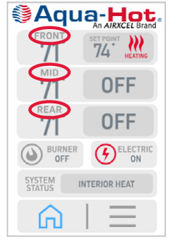
Modifying “Label” will change how the zone is displayed. There are three choices; Front, Mid, and Rear which correspond to the zones within the RV. See example below.
Filling the Aqua-Hot
Before the first activation of the Aqua-Hot, fill the unit with antifreeze and water heating solution. Without the solution present, the Aqua-Hot will not operate. Follow the directions below to fill the Aqua-Hot with antifreeze and water heating solution.
• Before filling the system, ensure all connections have been made and all clamps are tight.
- Pulling a vacuum within the system will not expose any leaks due to loose clamps.
• The fluid used in the AHM-125-D02 is a mixture of ethylene glycol and distilled water in a 50:50 ratio.
• It is strongly recommended to fill the AHM-125-D02 using a vacuum cooling system refill tool. Any air bubbles left by other fill methods can damage the burner.

Vacuum Fill Instructions
1. Remove the radiator cap from the top of the tank.
2. Attach the vacuum refill tool to the filler neck of the tank. The tool must seal below the overflow port on the filler neck to successfully pull a vacuum.
• The overflow port could be plugged if the tool doesn’t seal below the overflow port.
3. Attach a compressed air line to the tool following the manufacturer’s instructions.
4. Once a sufficient vacuum has been attained, close the valves. Let the system sit under vacuum. If the system holds vacuum proceed with filling. If not, diagnose and repair any leaks.
5. Attach the fill line to the tool and place the opposite end in a bucket filled with the fluid mixture.
• Do not fill directly from one-gallon bottles of fluid. Switching between bottles will introduce air into the system.
6. Open the valves letting the vacuum pull the fluid into the system. Once the gage reads zero vacuum, the system is full.
• During the first heat cycle of the system, any excess coolant will be vented through the overflow tube. Completely filling the tank and letting the excess fluid vent automatically will ensure the proper coolant level has been reached.
7. Turn pump on for 5 minutes.
8. Tap the three-way valve on the LCD to the other position.
9. Turn the pump on for another 5 minutes.
Alternate Fill Instructions
1. Remove the radiator cap from the top of the tank.
2. At the LCD screen tap the three lines icon -> Diagnostics -> Test -> Next

3. Tap the 3-Way Valve button until it says “Int heat”. Listen for the valve to stop moving.
• There is a window on the top of the valve showing a red line. This indicates the position of the valve and can be used to visually check when the valve has stopped moving.

4. Tap “Back” and tap the pump button. You should hear the pump turn on.
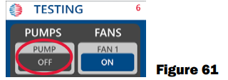
• The icon may say “UNDR CRT”. This will stop once coolant is poured into the tank.
5. Begin pouring the ethylene glycol distilled water mixture into the tank. Stop adding when the fluid reaches the bottom of the fill neck.
6. At the LCD screen in the Test menu tap the 3-way valve again until it displays “Hot Water”. You should hear some bubbles being released.
7. Tap the 3-way valve button again until it displays “Int Heat”
8. Let the pump circulate coolant for 10 minutes. The Test screen will time out after 5 minutes and the pump will have to be re-engaged.
Fuel System Purge
Fuel System Fill Procedure
Perform this procedure once the burner and Aqua-Hot are completely installed and the Aqua-Hot is adequately filled and purged.
• Ensure all fuel system connections have been made.
• Ensure all fuel line clamps are tight.
• The fuel level in the vehicle’s tank must be above the fuel pickup level.
• Provide adequate ventilation to prevent buildup of dangerous exhaust gases in the workspace.
Fill Instructions
1. At the LCD screen tap the burner switch to “ON”.

2. Listen for the fuel pump to start tapping. The pump will begin priming the fuel system.
3. If the burner does not receive fuel in time a fault will be displayed on the LCD screen. Tap the fault icon.
• If “Burner: Failed to Ignite” is displayed tap “RESET”. Follow the prompts to clear the fault. Wait approximately 30 seconds for the fault to fully clear before proceeding.
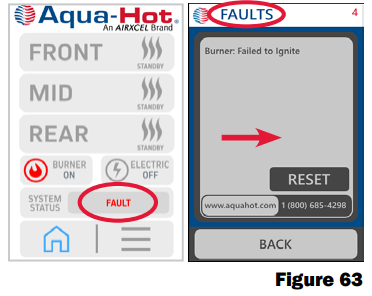
• If a different fault is displayed, follow the trouble shooting guide in the service manual and address the cause of the fault.
4. Repeat steps 1-3 until fuel reaches the burner. A rumble from the burner will be heard and the exhaust temperature will increase when the burner has ignited.
5. Tap the burner switch to “OFF”


Aqua-Hot First Operation
Activation Instructions (Electric Element):
1. Place a bucket under the tank overflow tube. As the tank heats for the first time after filling, any excess coolant will be vented through the overflow tube.
2. At the LCD screen, tap the electric switch to “ON”.

3. Tap the three lines icon --> Diagnostics --> Next

4. Locate the “Tank Thermistor” field.

5. Watch for the “Tank Thermistor” temperature to increase 2 to 3 degrees.
• If no temperature increase is seen, diagnose the electric element following the service manual.
6. Tap the Home icon --> Back --> Electric to OFF.
Activation Instructions (Burner):
1. Place a bucket under the tank overflow tube. As the tank heats for the first time after filling, any excess coolant will be vented through the overflow tube.
2. At the LCD screen, tap the burner switch to “ON”.

3. Listen for burner ignition, it can take around 1 minute to ignite.
4. Tap the three lines icon --> Diagnostics --> Next

5. Locate the “Tank Thermistor” field:

6. Watch for the “Tank Thermistor” temperature to increase 2 to 3 degrees.
• If no temperature increase is seen diagnose the burner following the service manual.
7. Allow the burner to heat the tank to full temperature (180°F).
8. Tap the Home icon Back Burner to OFF.

Interior Heating Zones
Procedure
1. At the LCD screen tap the burner switch to “ON” wait for the burner to ignite and boiler tank to heat up.

2. Ensure that each zone temperature readout is reasonable.
• If the zone temperature readout is incorrect, tap the three lines icon and check the temperature units are correct (Fahrenheit vs Celsius).
• Verify each zone is configured correctly.
• Check that the thermistors are wired correctly.
3. Tap on the first zone icon. Increase the temperature set point to 86°F. Tap “set”. Repeat for the remaining zones.
• If the interior temperature of the vehicle is higher than 86°F, the Cozy heaters will not turn on.
4. Go to each Cozy heat exchanger and make sure warm air is blowing.
• If no air is felt or cool air is felt, wait for the tank to heat up.
• If the ambient air temperature is higher than 86°F, the Cozy heaters will not operate.
• Refer to the service manual for diagnosis.
Hot Water System
Procedure
1. At the LCD screen, tap the burner switch to “ON” wait for the burner to ignite and boiler tank to heat up.

2. Individually turn each hot water faucet on making sure hot water comes from each faucet.
• If no hot water is produced, refer to the service manual for diagnosis.
Winterizing the Aqua-Hot
The Aqua-Hot’s domestic water heating system must be completely drained of domestic water at any time the heater is stored where freezing temperatures may be experienced. Please follow these instructions when winterizing the AquaHot domestic water heating system.

1. Completely drain the fresh water storage tank.
2. Disconnect the domestic water demand pump suction line from the fresh water storage tank.
3. Attach an adequate piece of hose onto the suction side of the domestic water demand pump.
4. Place the opposite end of the hose into an adequate supply of non-toxic RV winterization antifreeze (FDA certified as “GRAS” Generally Recognized As Safe must be used) and allow the fluid to pump through.
5. Open and close all interior and exterior water faucets one at a time, until ONLY pure RV antifreeze is present. Perform this procedure for both cold and hot water faucets.
6. Remove the hose and reconnect the domestic water demand pump’s suction line to the fresh water storage tank.

Disinfecting the Domestic Water System
The Aqua-Hot Heating components are not compatible to prolonged exposure to sodium hypochlorite (bleach or liquid bleach). Using products containing bleach, including water refreshers, may cause corrosion of the domestic water lines, resulting in a catastrophic failure of the Aqua-Hot system by creating leaks that cannot be repaired. This damage is not covered by the Aqua-Hot warranty.
If disinfecting the hot water system, be sure to follow NFPA 1192 Standard of Recreational Vehicles “Instructions for Disinfection of Potable Water Systems” or any other applicable local standards for Potable Water Systems.

System Schematics


Measuring Antifreeze Using a Refractometer


Parts & Accessories


Warranty
2-YEAR LIMITED WARRANTY AQUA-HOT® HYDRONIC HEATING SYSTEM
Aqua-Hot Heating Systems Inc. warrants the Aqua-Hot Heater to be free from defects in material and workmanship under normal use and service for a period of two years on both parts and labor commencing upon the original date of registration of the vehicle. Replacement parts are warranted for the remainder of the Heater’s standard warranty coverage or for six months, whichever is greater. The intent of this warranty is to protect the heater’s end-user from such defects, which would occur in the manufacturing of the product. Thus, problems due to improper specifications, improper installations, improper use, the use of accessory parts or parts not authorized by Aqua-Hot Heating Systems Inc., repair by unauthorized persons, and damage or abuse of the heater are specially excluded from warranty coverage.
For additional information, or to obtain a warranty repair authorization, please contact the Aqua-Hot Heating Systems Warranty Administrator at 574-AIR-XCEL (574-274-9235) (7:00 AM to 4:00 PM Mountain Standard Time) or visit www.aquahot.com.
My Comfort Zones are On-Board
Vehicle:
Purchased From:
Dealer Information:
Name:
Location:
Phone Number:
Heating System:
Serial Number: