Titan Leveling Systems Owner's Manual
Introduction
The Titan Leveling System™ is a hydraulic leveling system which includes four points of contact utilizing four jacks and a four-valve hydraulic system. A 12V DC electric motor drives a hydraulic pump that moves fluid through a system of hoses, fittings and jacks to level and stabilize the coach. Mechanical portions of the hydraulic leveling system are replaceable. This system is compatible with the Sprinter, Transit, and E450 Chassis. Contact Lippert to obtain replacement parts.
Additional information about this product can be obtained from lci1.com/support or by downloading the free LippertNOW app. The app is available on Apple App Store® for iPhone® and iPad® and also on Google Play™ for Android™ users. Apple App Store®, iPhone®, and iPad® are registered trademarks of Apple Inc. Google Play™ and Android™ are trademarks of Google Inc.
| Note: Images used in this document are for reference only when assembling, installing and/or operating this product. Actual appearance of provided and/or purchased parts and assemblies may differ. |
Safety
Read and understand all instructions before installing or operating this product. Adhere to all safety labels. This manual provides general instructions. Many variables can change the circumstances of the instructions, i.e., the degree of difficulty, operation and ability of the individual performing the instructions. This manual cannot begin to plot out instructions for every possibility, but provides the general instructions, as necessary, for effectively interfacing with the device, product or system. Failure to correctly follow the provided instructions may result in death, serious personal injury, severe product and/or property damage, including voiding of the Lippert limited warranty.
Prior to Operation
The leveling system shall only be operated under the following conditions:
- The coach is parked on a reasonably level surface, engine running.
- The coach “parking brake” is engaged.
- The coach transmission should be in the park position.
- Be sure to keep hands and other body parts clear of fluid leaks. Oil leaks in the Lippert Leveling System may be under high pressure and can cause serious skin penetrating injuries.
- Never lift the coach completely off the ground. Lifting the coach so the wheels are not touching ground will create an unstable and unsafe condition.
| Warning: Lifting all wheels off the ground may result in serious personal injury or death. |
LED Touchpad Controller Operation
NOTE: The LED Touchpad Controller is only ON while the coach ignition is ON, no operation of leveling will be allowed without ignition source. Parking Brake MUST be engaged for the system to operate.
- Figure 1 is the default screen when coach ignition is ON and assigned to the “Home” icon (Fig. 1A).
- Figure 2 is assigned to “Menu” icon (Fig. 2A).
- (Fig. 2B) MANUAL MODE ability to extend jacks in pairs.
- (Fig. 2C) CONNECT APP with phone Bluetooth on, click button to search on phone for “Auto Level, Titan Leveling Systems” or similar.
- (Fig. 2D) CALIBRATION is a required step to program the control's orientation and define a level plane. Initial calibration will be set by OEM but operator may perform calibration again at a later date to ensure the system is at a level plane.
- (Fig. 2E) JACK LIGHTS on/off button, turns on all LED lights located on the front and rear crossbars, close to each of the jacks. Lights are optional and this button may not be used.

- Figure 4 is assigned to “Manual Mode” button from menu screen (Fig. 2B). Each button, ex. Extend Front (Fig. 4A) is a button that operates both front jacks. Each button is a pair of jacks and only extends the jacks.
- Figure 3 is the screen displayed during the leveling process.

- During the, “Auto Level” process, (Fig. 1B), control sensed movement in the coach during leveling process, too much time has passed or if control was calling to extend pair of jacks but saw zero movement (angle change) meaning the cylinders have reached full stroke, or coach is parked on too great of an incline (typically over 6 degrees) and cannot complete level process. The "Leveling Error" screen (Fig. 5) will appear. Press Home (Fig. 5A) or Menu (Fig. 5B) icons to get out of this page.
- During the, "Retract Jacks" (Fig. 1C), or in "Manual Mode", (Fig. 2B), Figure 6, "Jacks Are Retracting" screen is displayed.

- Figure 7, "Parking Brake Error", will appear when no parking brake signal is received and there is no pressure switch signal indicating jacks are still retracted. Screen prompted before auto level and manual mode functions. Screen prompted for five seconds, then returns to home screen (Fig. 1). If jacks are extended and parking brake signal is lost, jacks will automatically retract.
- Figure 8, "Insufficient Voltage", screen may be prompted before or during “Auto Level”, “Retract Jacks” or “Manual Mode” functions. This screen is prompted when the control is receiving less than 10.7 volts.

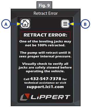
- "Retract Error" screen (Fig. 9) will appear with ignition on and touchpad on or in “sleep” mode (display off, power to control still on). If the control receives signal from the pressure switch (meaning the internal pressure of the hydraulic system has dropped below 2,150 psi, connection lost from pressure switch to control) the control enters retract all mode. If pressure switch does not open back up after 10 seconds, the audible alarm may be prompted (2 seconds on, two seconds off, 70-85 decibels), jacks will stop retracting and this screen will be displayed. Alarm will run until coach ignition is off or pressure switch opens up indicating that optimal pressure is reached. Home (Fig. 9A) or Menu (Fig. 9B) icons can be pressed to silence the alarm. DO NOT ignore this alarm. There may be a jack down or component failure, possibly making it dangerous to drive. Operator can use the home or menu icon and reach “retract jacks” function.
- Figure 10, "Level Success!" screen is prompted after auto level feature has successfully completed. Accompanied by an audible chime (3 seconds long). Screen stays active for 5-10 seconds, then returns to home screen (Fig. 1).

Troubleshooting
Manual Override - Jacks
In the event that the jacks will not extend or retract, the valves can be manually overridden by using a 5/32” or 5/64" hex wrench to turn the manual override clockwise on the valve (Fig. 11). The leveling jacks can then be extended or retracted. Remember to turn the manual override completely counterclockwise (Fig. 12) until it will no longer turn to close the valve after the jacks have been completely extended or retracted.

Manual Override - Power System
The Lippert Electronic Leveling System can be run with auxiliary power devices including electric drills, ratchet wrenches or cordless screwdrivers. In the event of electrical or system failure, this manual method of extending and retracting the jacks can be used. A standard handheld drill is all that is required.
- Remove plastic cap (Fig. 13A).
- Disconnect power cables on the motor.
- Using a 1/2” socket, insert into auxiliary drive device, i.e. cordless or power drill. Insert socket onto coupler found under plastic cap (Fig. 14A).
- Run drill in reverse or counterclockwise to retract jacks.

Audible Alarm Modes
- Parking brake alarm, enabled from software while ignition is on, display is in sleep mode or on, related to loss of signal from parking brake (user dis-engages parking brake) while pressure switch signal is received (jacks are down). Alarm to sound two seconds ON, two seconds OFF, repeat until ignition off or signal is received from parking brake or signal is lost from pressure switch (indicating jacks retracted) for software to shut off alarm.
- Leveling complete chime, small collection of chimes or light beeps to indicate to user that leveling has successfully completed, can be tied to “Leveling Success!” screen. Only few seconds long.
Preventative Maintenance Procedures
- Change fluid in RESERVOIR ONLY when contaminated.
- Check fluid only when jacks are fully retracted.
- Always fill the reservoir with the jacks in the fully retracted position. Filling reservoir when jacks are extended will cause reservoir to overflow into its compartment when jacks are retracted.
- When checking fluid level, fluid should be within ¼” of fill spout lip.
- Check the fluid level every month.
- Inspect and clean all pump electrical connections every 12 months. If corrosion is evident, spray coach with WD-40 or equivalent.
- Remove dirt and road debris from jacks as needed.
- If jacks are down for extended periods, it is recommended to spray exposed leveling jack rods with a silicone lubricant every three months for protection. If your coach is located in a salty environment, it is recommended to spray the rods every 4 to 6 weeks.
Fluid Recommendation
ATF with Dexron III® or Mercon 5® or a blend of both is recommended by Lippert. Type “A” Automatic Transmission Fluid (ATF) is utilized and approved. Hydraulic system operation in climates at or below 40 degrees F (4 degrees C) may result in the following:
- Slow operation during extension/retraction
- Incomplete retraction of jacks during Auto Retract procedure For a list of approved fluid specifications, see TI-188.
Level Zero Point Calibration
The Zero Point Calibration has been set by the RV manufacturer and verified by the RV dealer. If a new zero point is desired, proceed with this section. The “Zero Point” is the programmed point that the trailer will return to each time the Auto Level feature is used. The “Zero Point” must be programmed prior to using the Auto Level feature to ensure the proper operation of the system. This mode is enabled by performing the following sequence:
- Go to the Menu button (Fig. 15A) and select the Calibration button (Fig. 15B).
- Select the arrow on the touchpad that is the direction of the display of the touchscreen is facing related to the coach (Fig. 16).

- Follow the directions on the next screen (Fig. 17) to calibrate the LED touchpad controller. Place a level on the floor of the coach to ensure a level reference point in the coach. Press “LEVEL VEHICLE” on the touchpad.

- The next screen that follows (Fig. 18) shows four extend buttons that activate each pair of valves, directional control valve and solenoid. The "CONFIRM LEVEL" button is a latching button that zeros out the control accelerometer and stores that exact position as level. After the initial calibration, when the user presses “AUTO LEVEL”, the control recognizes that position as level and will bring the coach to that position.
- Level the coach in the manual "CALIBRATION" mode by using a carpenter’s level on the floor. Level front to rear and then left to right.
- Push the "EXTEND FRONT" (Fig. 18A) button until jacks contact the ground and lift the front of the coach 1-2 inches.

- Push "EXTEND REAR" (Fig. 18D) button until jacks contact the ground and lift rear of coach. Continue to use EXTEND REAR and EXTEND FRONT buttons until the carpenter's level bubble is centered.
- Push "EXTEND DRIV SIDE" (Fig. 18B) and "EXTEND PASS SIDE" (Fig. 18C) buttons until level bubble is centered.
- With the coach leveled, press “CONFIRM LEVEL” (Fig. 18E).
- The touchpad is now in zero mode. If the coach has come out of its level condition, it can be reset into level condition by following the procedure outlined in step 3.

Solutions to Possible System Errors
| What Is Happening? | Why? | What Should Be Done? |
|
System will not turn on.
|
Coach ignition not in RUN position. | Turn ignition to RUN position. |
| Parking brake not set. | Set parking brake. | |
| Controls have been on for more than four minutes and have timed out. | Tap screen or turn ignition off and then back on. | |
| Touchpad turns on, but turns off when a jack button is pushed. | Low voltage on battery. | Start coach to begin charging battery. |
| Plug vehicle in to charge house battery. | ||
| Touchpad turns on, coach will not auto level. | Faulty pressure switch or low pressure in system. | Check parking brake is engaged. |
| Re-calibrate level position. | ||
|
Jacks will not extend to ground, pump is running. |
Little or no fluid in reservoir. | Fill reservoir with recommended ATF. |
| Jack valve is inoperative. | Clean, repair or replace. | |
| Electronic signal is lost between controller and jack valves. | Trace wires for voltage drop or loss of signal. Repair or replace necessary wires or replace controller. | |
|
Any one or two jacks will not retract.
|
Hose damaged or disconnected. | Replace with new hose or reconnect hose. |
| Return valve inoperative. | Replace inoperative return valve. | |
| Electronic signal is lost between controller and solenoid. | Test for voltage drop between controller and jack valve. Repair bad wiring or replace defective controller or valve. | |
| Jack bleeds down after being extended. | Valve manual override open. | Close override. |
|
No power to touchpad. |
Tripped circuit breaker. | Reset breaker. |
| Ignition not on. | Turn on. |