Freedom Inverter Owner's Guide
Freedom Inverter/Charger Operation
Start Up Behavior
When the Freedom SW is powered up or has been reset, all of the front panel LEDs turn on and remain on for a minimum of five seconds. During this interval, the fans are also turned on as the unit executes internal diagnostics.
Out of the box from the factory, when the Freedom SW is powered up (that is, when AC and DC power sources are connected) for the first time, the inverter function is disabled by default. After powering up, the INVERTER ENABLE button (or the “Up” button on the SCP) can be used to enable or disable inverter function. See “Inverter Operation Using the Front Panel” and “Enable/disable inverter function (EnInv/DsInv)”.
Storing Inverter State Feature
You can enable or disable a feature called StoreInvState which, when enabled remembers the state of the inverter function prior to a power down (that is, when AC and DC power sources are disconnected) or prior to a Standby (Power Save) mode. When the Freedom SW is powered up again or put back on Operating mode, the inverter function reverts back to its prior state. See “To store the state of the inverter to memory:”. This feature is disabled by default. This feature is available only to Freedom SW 2024 (PN: 815- 2024). Enable versus Disable When a function is enabled, it is allowed to occur but other conditions may have to be met before the function actually works. For example, the charger function on the Freedom SW may be enabled, but will not charge the battery unless qualified AC power is present. For more information, see “Enabling a function” and “Disabling a function”.
Inverter Operation Using the Front Panel
Once the inverter/charger is installed, you can operate it in invert mode. To operate in invert mode from the front panel:
- Press the INVERTER ENABLE button on the Freedom SW on the front panel. The INVERTER ENABLED LED turns on and connected loads will be energized.
- Note that if AC is present and being passed through, the INVERTER ENABLED LED will still turn on to indicate inverter mode has been enabled. However, AC will continue to be passed through to the loads until conditions exist that cause AC to be disqualified, in which case the unit will transition to invert mode and power up critical loads.
- Connect AC input power. The charger automatically starts up when qualified AC power is connected. To operate the inverter with the System Control Panel, refer to “Operating the Freedom SW with the SCP”.
- Disconnect AC power from inverter input by opening the breaker or disconnect.
- Place a load on the inverter. For example, plug a 100-watt light bulb into an outlet that the inverter is powering. Press the INVERTER ENABLE button on the Freedom SW. The INVERTER ENABLED LED turns on. The inverter should run the load using battery power.
- To test the charger, reconnect the AC input power to allow AC to the AC input. The AC In/Charging LED should start flashing after a brief delay. Any AC loads previously powered by the inverter will also work at this time. NOTE: On dual input models, only AC Input L1 needs to be powered for the unit to operate.
- Remove the AC input power. The inverter/charger should transfer to invert mode immediately. (The transfer relay will make a clicking sound and the INVERTER ENABLED LED will turn on.) Loads should continue to operate uninterrupted. If any part of this test fails, determine the cause before using the unit.
- Monitor the Freedom SW Front Panel. The indicator LEDs on the front panel show you the operating status of the Freedom SW. A description of the LEDs is provided in Table 1. If none of the front panel LEDs are on, see “Troubleshooting”.
| Table 1 Front Panel LEDS | |||
| LED Label | Color | Status | Action (or Status Item) |
| Inverter ENABLED | Steady Green | If utility and generator AC is unavailable and operating conditions are met, the Freedom SW will produce AC voltage to power loads. | You can run your appliances from the inverter. |
| Gen Support | Flashing Green | The inverter is assisting a generator in powering loads. | You can run your appliances from the inverter. |
| AC In | Steady Green | When the Freedom SW is connected to a qualified AC source or a generator, the AC IN LED turns on. | You can run your appliances from an AC source like the utility grid or a generator. |
| Charging | Flashing Green | Freedom SW is connected to a qualified AC source, is charging and passing power to AC loads. | Your battery bank is being replenished and AC loads are receiving power. |
| Fault | Steady Red | A fault condition was detected on the network. | Investigate and clear the fault condition. |
| Warning | Flashing Red | A warning is detected. | Investigate by examining warning logs on SCP. |
Faults and Warnings A fault affects the operation of the unit. A manual fault requires user intervention by clearing the condition and then pressing the CLEAR FAULT RESET button on the inverter/charger’s front panel. See the Xanbus System Control Panel Owner’s Guide for information on clearing faults from the SCP. A warning alerts you to a condition that could possibly affect operation of the unit.
Operating Limits for Inverter Operation
Temperature
The Freedom SW series of inverter/chargers will operate at rated power continuously at 30 °C with some models capable of continuous operation at much higher ambient temperature. However, the continuous power rating at elevated ambient temperature may differ between models. See “Specifications” for full details. In higher ambient temperatures, if the loads draw full power for an extended period of time, the unit may shut down to protect itself against overheating.
The Freedom SW series of inverter chargers feature a surge rating of 200% of rated power for five seconds at 25 °C. Operating the inverter/charger in conditions outside of power and temperature limits, however, will result in thermal shutdown and/or significantly decreased performance. In addition, operation in this range is outside the ratings covered by the regulatory approvals of the product.
Difficulty on starting loads
The inverter/charger should be able to operate all AC loads rated at or below its power rating. Some high horsepower induction motors used in pumps and other motor-operated equipment require very high surge currents to start, and the inverter/charger may have difficulty starting these loads.
If you have problems starting certain loads, ensure that:
- Battery connections are tight and clean.
- DC cabling is no longer than the recommended length. Refer to the Freedom SW Sine Wave Inverter/Chargers Installation Guide for this information.
- AC wiring is of recommended size. Refer to the Freedom SW Sine Wave Inverter/Chargers Installation Guide for this information.
- Battery is of sufficient capacity and is fully charged.
Operating Limits for Charger Operation
By default, the maximum charger output current is the rated charger output current for the particular model. Using the SCP, you can reduce the total output if you change the maximum charge rate (Max Chg Rate) on the Freedom SW Basic Settings menu or Inverter Settings menu under Advanced Settings. The charger can operate within an AC input range of 95–135 volts. The default settings are 95 and 135, which are the ACIn Lo Volt and ACIn Hi Volt respectively. The ACIn Lo Volt setting has a range of 78–115 volts and the ACIn Hi Volt setting has between 125–140 volts.
AC Frequency
The charger can also be configured to accept and operate from a wide AC source frequency of 40– 68 Hz. Therefore, the Freedom SW can charge your batteries even when incoming AC voltage is less than ideal. The default settings are 45 and 55 Hz, which are the ACIn Lo Freq and ACIn Hi Freq settings respectively.
Power sharing
The Freedom SW charger uses incoming AC or shore power (see following note) to charge the batteries. The charger shares incoming AC power with AC loads on Line 1 only. The AC loads have priority, which means that the charger will reduce its output with large AC loads and increase the output again when the AC load decreases. The regulatory maximum for continuous AC loads is 80% of the breaker rating (see “AC1 Breaker”) that the loads are connected to. The Freedom SW senses passthrough current going to the AC load. The difference between the pass-through (load) and 80% of the AC1 Breaker setting is the current that is available for charging the batteries. For example, if the AC input of the Freedom SW is from an AC panel with a 30-amp breaker, the AC1 Breaker setting on the SCP should be selected as 30 amps. Based on this, the charger will control the charge current so that the total current draw is equal to or less than 24 amps in this case. Should the load current be more than 24 amps, the charger output will reduce to 0 amp, but the Freedom SW will continue to supply the loads. The Freedom SW will continue to pass-through power to the loads, even if the load current exceeds the AC1 Breaker setting. In this case, it will be up to the user to remove/disconnect loads if tripping the AC input breaker supplying the Freedom SW is to be avoided.
Operating the Freedom SW with the SCP
This section contains detailed information and procedures for using your Freedom SW in conjunction with the System Control Panel (SCP). If you’re using the SCP to operate or monitor the status of the unit, you may also refer to the Xanbus System Control Panel Owner’s Guide.
The SCP provides operating, configuration, and monitoring capability for your Xanbus system.
The SCP:
- Monitors activity throughout your onboard power system.
- Displays the latest information about your inverter/ charger, battery voltage level, battery charge output, and generator start and stop activity.
- Displays the settings for each Xanbus-enabled device in the system.
- Enables you to adjust the settings for each Xanbusenabled device in the system.
- Preserves all of its settings if system power is interrupted. After power is restored, you don’t have to reconfigure the SCP or any of the Xanbus-enabled devices connected to it.
This section provides information on operating the Freedom SW with the SCP. Please refer to the System Control Panel Owner’s Guide for complete information on using the System Control Panel.
Using the Xanbus SCP
As shown in Figure 8, the SCP has these important features:
- Display screen: System information is shown on the display screen with an adjustable backlight.
- Indicator LEDs: Four indicator LEDs on the front panel indicate the operating status of the Xanbus system.
- Push buttons: Four push buttons allow you to select device menus and change or display settings. The red STBY/ON Fault Clear button toggles the SCP and Xanbus-enabled devices between Operating mode and Standby (Power Save) mode, if held down for more than five seconds. The button can also be used to clear any active faults or warnings by momentarily depressing the button.
System Control Panel
The Xanbus System Control Panel (SCP) provides configuration and monitoring capability for all Xanbusenabled devices on the network. All changes to the configuration of the Freedom SW are made with the SCP. The front panel of the Freedom SW provides limited control, including reset; charger enable and disable; and inverter enable and disable.
- Enabling a function: When a function is enabled, it is allowed to occur but other conditions may have to be met before the function actually works. For example, the charger function on the Freedom SW may be enabled, but will not charge the battery unless qualified AC power is present.
- Disabling a function: When a function is disabled, it is not allowed to occur and if it is already occurring, it is terminated immediately. Regardless of other conditions, the function will not work. For example, even if AC power is present, if the charger function is disabled, the Freedom SW will not charge the battery.

| Item | Description |
| 1 | AC In/Charge LED indicates that qualified AC is present at the input of an inverter/charger. When the Freedom SW is connected to a qualified AC source like the utility grid or a generator, this LED on the SCP turns on. |
| 2 | Inverter On LED turns on when the Freedom SW is inverting using battery power. |
| 3 | Low Battery LED turns on when the battery voltage on the Freedom SW is low. |
| 4 | Fault LED indicates a detected condition that requires user attention and intervention. The Fault LED turns on when any Xanbus-enabled device connected to the network detected a fault. See “Detected Fault Types” for the definitions of a fault and warning. |
| 5 | STBY/ON Fault Clear button is used to clear active faults on the system if pressed momentarily. It also toggles all Xanbus-enabled devices on the system between Operating and Standby (Power Save) mode when held down for more than five seconds. See “Inverter Operation Using the Front Panel”. |
| 6 | Screen displays menus, settings, and system information. Displays a menu screen title, four lines of menu items, and a line that contains small arrows that depict pointers to SCP buttons. |
| 7 | Func button: Cancels selection of a menu item. Returns you to the previous screen. Changes the functions of the Up and Down arrow buttons. |
| 8 (and 9) |
Down (and Up) arrow buttons: Scrolls down (up) one line of text. Decreases (increases) a selected value. When the Func button is pressed to select:
|
| 10 | Enter button: Confirms selection of a menu item. Moves you to the next screen. |
SCP Navigation
Startup Screen
This screen is shown when the Xanbus SCP first receives power from the Xanbus network.

Viewing the SCP Home Screens The top level screens on the Xanbus SCP are the startup screen, the System Status screen (Figure 10) and the device Home screen. After power is applied and the startup screen appears, the Xanbus SCP displays the System Status screen. You can view the device Home screen for the Freedom SW and other devices in the system by pressing the up and down arrows.

System Status Screen
- The System Status screen appears after the startup screen. It displays aggregated status information for the entire power system. For example, a single system might have two Xanbus network-connected Freedom SWs, one Xanbus AGS module, and one Xanbus SCP all connected to a single battery bank. The System Status screen always features a menu arrow pointing to the Enter button. Pressing Enter takes you to the Select Device menu screen. For more information, see “Reading the System Status Screen”.
Select Device Screen
- As mentioned, this screen appears when the Enter button is pressed from the System Status screen. It lists all Xanbus-enabled devices including options to select System Settings and Clock.

To display the Select Device menu:
- While viewing the System Status screen, press Enter.
Device Setup Screen: The Device Setup screen is shown when a Xanbus-enabled component is selected from the Select Device screen. For example, below is an example of a Device screen for the Freedom SW 3012 inverter/charger. Device Setup menus display status information and changeable settings. Changeable settings are identified by the square brackets [ ] around values in the right-hand column.
To display the Setup menu for a device:
- Highlight the device name on the Select Device menu screen and press Enter. -Or, from the device Home screen, press Enter.

Soft Key Navigation
Soft keys are the objects on the fifth line of the System Status screen. The soft keys have arrows that point to a corresponding physical button such as the Enter, Up arrow, Down arrow, and Func buttons. They are called as such because they perform functions in conjunction with pressing the corresponding SCP button that each arrow points to.

In the next page, it will show how to navigate the soft keys to:
- Enable/disable inverter function (EnInv/DsInv)
- Enable/disable charger function (EnChg/DsChg)
- Change shore breaker ratings (Shr) - see also “AC In Breaker”
- Select AGS trigger modes (AGS)

Viewing the Firmware Revision Number
You may need to view the firmware revision number (F/W Rev.) of the Freedom SW when troubleshooting the unit with authorized service personnel.
To view the firmware revision number:
- From the System Status screen, press the Enter button. The Select Device menu screen appears.
- From the Select Device screen, press the Enter button. The System Settings menu screen appears.
- From the System Settings screen, press the down arrow button to highlight View Device Info
- Press Enter. The Device Info screen appears.
- Read the displayed information. The series of numbers and letters opposite F/W Rev. is the firmware revision number.
- Press Func (3x) to return to the System Settings menu.

Setting the Time and Date
Freedom SW advanced features such as time-stamped events (faults, warnings, and logged historical data) require that the system be set to the correct time. The Xanbus SCP has an internal clock that controls the time for all Xanbus-enabled devices in the system. You can set the time, time format, and date on the Clock menu. The Clock menu is accessible on the Select Device menu.
Using the STBY/ON Fault Clear Button
The STBY/ON Fault Clear button has two functions. The STBY/ON Fault Clear is used to clear active faults on the system if pressed momentarily. It also toggles all Xanbus enabled devices on the system between Operating and Standby (Power Save) mode when held down for more than five seconds.

Reading the System Status Screen
The System Status screen displays:
- Battery-related information (see Line 2)
- Battery level and inverter/charger operating state (see Line 3)
- Load information (see Line 4)
- AC Input information (see Line 5)

| Line 1 | Label: “System Settings” |
| Line 2 |
Label: Battery Field 1: Total battery current. Negative value if the battery is discharging and positive value when charging. Field 2: Battery voltage Field 3: Battery temperature . Also, displays the highest temperature between stacked inverters that are installed. |
| Line 3 |
Label: BatLev Field 4: Displays a bar graph showing the approximate battery level. Field 5: Freedom SW inverter/charger operating state |
| Line 4 |
Label: Load Field 6: Inverter output voltage at load terminals of the inverter/charger. Voltage is reported by the Master unit if more than one inverter/charger is installed. Field 7: Master current Field 8: Sum of all load current from both inverter and charger. Also, it displays Slave (or L2 Master) current. |
| Line 5 |
Label: AC In Field 9: AC input voltage at AC In terminals of the inverter/charger. Voltage is reported by the Master unit if more than one inverter/charger is installed. Field 10: Master current Field 11: Sum of all L1 AC input current from both inverter and charger. Sum of all load current from both inverter and charger. Also, it displays Slave (or L2 Master) current. |
Reading the Freedom SW Device Setup Screen
The Freedom SW Device Setup menu screen displays real-time operational data (status information) specific to the Freedom SW. The Freedom SW status changes according to the states described in Table 4, “Freedom SW Device Setup Screen Operating States (Modes)”.
The Freedom SW Device Setup menu screen has two segments. The first segment (lines 2 to 5) displays status information and appears first in the screen’s initial four lines. The second segment (lines 6 to 15) contains selectable fields when the Down arrow button is pressed (scrolling down the device setup screen). These selectable fields are configurable, meaning their values can be changed from within the setup screen or they bring up another screen (another level of configuration). For information on how to configure the Freedom SW inverter/charger, see “Configuring the Freedom SW using the SCP”.
To view the Freedom SW Setup menu screen:
- On the Select Device screen, press the Down arrow button until the FSW3012 001 is highlighted.
- Then, press Enter to display the FSW3012 00: Setup screen which is the device setup menu screen.
- Press the Up and Down arrow buttons view status information fields and move between selectable fields.


Table 3 Device Setup Screen Status Information |
| Line 1 | Label: “FSW3012 00: Setup” |
| Line 2 |
Label: Mode Field 1: Freedom SW operating mode or “operating state” |
| Line 3 |
Label: Battery Field 2: Total battery current. Negative value if the battery is discharging and positive value when charging. Field 3: Battery voltage Field 4: Battery temperature. Displays the highest temperature when reading two inverters that are installed. Displays N/A when there is no BTS attached. |
| Line 4 |
Label: Load Field 5: Total power drawn by AC loads connected to the unit. Field 6: Inverter output voltage at load terminals of one inverter/charger unit. Field 7: Sum of all current drawn out by the AC loads. |
| Line 5 |
Label: AC In Field 8: AC input voltage at AC In terminals of the inverter/charger. Field 9: Sum of all current drawn into one inverter/charger unit. Field 10: AC input frequency |
| STBY/On Fault Clear | Press momentarily to clear all faults on all devices on the network. Press and hold for five seconds to switch all devices in the network between operating and standby modes. |
|
Enter,Up arrow, Down arrow buttons (Pressed Simultaneously) |
Switches between Basic Settings and Advanced Settings. |
Table 4 Freedom SW Device Setup Screen Operating States (Modes) |
| State (Mode) | Displayed When... |
| Invert | The Freedom SW is supplying power to loads by inverting power from the batteries. AC input from the utility or generator is absent or out of nominal range. |
| Qualifying AC | The Freedom SW is determining if AC input is within a usable voltage and frequency range. Qualifying AC is also displayed when the Freedom SW is awaiting application of AC power or a command to enable invert mode. |
| Charging | The Freedom SW is charging the batteries from qualified AC input from the utility grid or a generator. The charge state is in transition to either bulk, absorption, float, or equalize. AC input is also passed through to the load while charging. |
| Bulk | The Freedom SW is bulk charging the batteries from qualified AC input from the utility grid or a generator. AC input is also passed through to the load while bulk charging. |
| Absorption | The Freedom SW is absorption charging the batteries from qualified AC input from the utility grid or a generator. AC input is also passed through to the load while absorption charging. |
| ABS Finish | One Freedom SW unit has completed the absorption stage and is waiting for other Freedom SWs in the system to complete absorption. This status can occur only when there is another Freedom SW also charging the battery. |
| Float | The Freedom SW is float charging the batteries from qualified AC input from the utility grid or a generator. The Freedom SW is set for three-stage charging. AC input is also passed through to the load while float charging. |
| Fault | The Freedom SW has an active fault. The Fault/ Warning LED on the Xanbus SCP is on. |
| Gen Support | There is AC input from the generator, and the Freedom SW is supporting the generator by supplying additional power to the critical loads. See “Gen Support” |
| Search | Search mode is enabled and the Freedom SW is standing by, waiting to begin inverting. See “Changing Configurable Settings From The Device Setup Menu Screen” |
| Passthru | The AC connected to the AC1 or AC2 input is passing directly through the Freedom SW to the loads. The batteries are not being charged in this state. |
| Equalize | Equalization has been turned on and the Freedom SW is equalizing the batteries after completing a full charge cycle. |
Configuring the Freedom SW using the SCP
This section contains information about all configurable settings and procedures for the Freedom SW. It provides information on using the SCP to configure the Freedom SW settings for optimal performance. Please refer to the Xanbus System Control Panel Owner’s Guide for detailed information on how to use the SCP.
System Menu Map
Figure 16 provides a map of how the SCP screens and menus are organized. The order of devices appearing on the SCP will vary, depending on the order in which they’ve been connected to the network.

Viewing the System Status Screen
The System Status screen displays system activity. The information appearing on the System screen varies with the status of the inverter/charger. See “Reading the System Status Screen”. Go back to “Reading the Freedom SW Device Setup Screen” for an explanation of the different states of the inverter/charger. For example, Figure 17 shows the Freedom SW in the bulk stage of charging.

You cannot select or change any of the information on the System Status screen. If you would like to view more detailed information, press the Enter button (indicated by the menu arrow) to go to the Select Device menu.
Viewing the Select Device Menu
The Select Device menu is where you can view a list of all the Xanbus-enabled devices in your power system. At least two devices are sure to appear together with System Settings and Clock – the Freedom SW Inverter/Charger and the Xanbus SCP. Other devices such as the Xanbus AGS and the Freedom Sequence Intelligent Power Manager appear only when they are connected and installed.

Selecting the Freedom SW from the Select Device Menu
To view the Freedom SW Setup menu screen:
- Follow the procedures on “To view the Freedom SW Setup menu screen:”

You can view and change Freedom SW settings from the Setup menu screen. The Basic Settings and Advanced Settings bring up their menu screens for which other configurable settings can be found.
Changing Configurable Settings From The Device Setup Menu Screen
The Freedom SW can only be configured using the Xanbus SCP. Follow the procedure in “To view the Freedom SW Setup menu screen:” to bring up the device setup screen for the Freedom SW inverter/charger.

As discussed in “Reading the Freedom SW Device Setup Screen” the Freedom SW Device Setup menu screen has two segments. The first segment (lines 2 to 5) displays status information and appears first in the screen’s initial four lines. The second segment (lines 6 to 15) contains selectable fields which are configurable settings.
These configurable settings are:
- Advanced settings
- Inverter
- Search mode
- Charger
- Force charge
- Equalize
- Desired mode
- Clear fault settings
- View device info
- Basic settings
Only nine of these settings are displayed at a time. The Advanced Settings (Line 6) is not initially listed and only lines 7 through 15 appear. When the Advanced Settings is listed, it will appear on top of the list for configurable settings and the setup screen will display lines 6 through 14. See Table 5, “Configurable Settings” for information on each setting.
To select and change a configurable setting:
- On the setup menu, press the Down arrow (or Up arrow) button to highlight the setting you want to change.
- Press Enter to highlight the current value of the setting.
- Press the Up arrow or the Down arrow button to change the value. Hold down the button to scroll through a large range of values quickly. The previously set value (or default value) appears with an asterisk (*) beside it.
- Press Enter to select and confirm the value.
- If you have another setting to change, return to step 1. -OrIf you have no more settings to change, press Func until the Xanbus SCP displays the desired screen or menu.

Table 5 Configurable Settings |
| Item | Description |
| Inverter | Enables or disables the inverter function of the Freedom SW. When enabled, the unit will invert power from the batteries assuming there is enough charge in the batteries. Default value is Enabled. |
| Search Mode | Enables or disables the Search Mode function of the Freedom SW. See “Using Search Mode” for more information. Default value is Disabled. |
| Charger | Enables or disables the charger function of the Freedom SW. When enabled, the unit will charge the batteries when AC is available. For more information on configuring the charger settings go to “Charger Settings Menu”. Default value is Enabled. |
| Auto Chg Enable | Forces the Freedom SW to charge the batteries when qualified input AC is detected even when the charger function is disabled. |
| Equalize | Initiates the battery equalization process. See “Equalization Procedure” to enable the procedure. Default value is Disabled. |
| Desired mode | Switches between Operating and Standby (Power Save) modes. Default value is Operating. |
| Clear Faults Warning | Clears any active faults and warnings. |
| Basic Setting | See “Changing Freedom SW Basic Settings” for more information. |
| Advanced Settings | See “Changing Freedom SW Advanced Settings” for more information. |
Using Search Mode
Why use Search mode?
- Search mode allows the inverter to selectively power only items that draw more than a certain amount of power, which can result in power savings. The Freedom SW has a no-load power draw of about 28 watts. Enabling search mode reduces this power draw to less than 8 watts. Search mode operates differently in single-unit and multi-unit installations.
Single units
- When a single Freedom SW has search mode enabled, the inverter sends electrical search pulses through its AC output. These search pulses look for connected AC loads. The delay between search pulses is set using the Search Delay setting. After a load larger than the Search Watts setting is detected, the inverter starts producing AC output.
Double units
- When configured for 120/240-volt series stacking, each inverter/charger operates independently in search mode and attempts to detect loads connected to its terminals only. To use search mode in parallel stacking, the Master unit must have Search Mode disabled. The Slave unit must have Search Mode enabled.
When to set up Search mode
- The search mode feature is only valuable if the inverter can spend a fair amount of time “sleeping” each day. Therefore, if search mode is to be used it must be adjusted properly. The initial adjustment should be made so that the inverter comes on only when needed. Certain types of loads can cause search mode to work unexpectedly. These types of loads are described in “Inverter Applications” on page 88. If these kinds of loads are in the system, follow the suggestions given to eliminate the problem.
If the problem loads cannot be eliminated, there are two work-around solutions:
- Disable search mode from the main Freedom SW Setup menu, causing the inverter to always remain at full output voltage.
- Use a search-friendly companion load whose only purpose is to be switched on to wake up the inverter to power the load that is unable to bring the inverter out of search mode.
Equalization Procedure
To start equalizing the batteries, do one of the following:
- Apply AC voltage and ensure that the inverter/charger transfers AC and starts charging.
- On the Xanbus Setup menu, highlight Equalize and select Enable. The unit will proceed and execute a complete bulk and absorption charge before transitioning to equalize. IMPORTANT: The inverter/charger will not perform equalization if AC is not present, the charger is disabled, or the selected battery type does not support equalization. If any of these cases happen, a warning is issued.
If the Freedom SW will not perform the equalization, see“Detected Warning Types and Behavior".
Changing Freedom SW Basic Settings
Basic Settings menu
- The Freedom SW configuration settings can be viewed in basic format (see “Selecting Basic Settings From the Device Setup Screen” on page 49). The basic settings include configuration items you may have to adjust routinely, or as part of initial setup. It provides access to basic control of the inverter/charger.
Temporary versus permanent
- The Freedom SW unit stores its configuration in its onboard memory which holds configuration values even during power cycling or restart events. The Freedom SW allows the user to make changes to the configuration settings at any time the unit is powered and communicates with the SCP or a Xanbus configuration tool. This is true for Basic Settings as well as Advanced Settings.
- Any configuration setting changes will be temporary, that is, they will be lost after a power cycle or restart. In order to make the setting permanent, they must be saved in the onboard memory by placing the unit in Standby (Power Save) mode. For instructions on how to put the unit in Standby (Power Save) mode, see “Using the STBY/ON Fault Clear Button”. While the unit is in the Standby (Power Save) mode the configuration changes will be immediately saved in the onboard memory. For more information on operating states (modes).
To select the Basic Settings menu screen:
- On the FSW3012 00:Setup screen (Figure 22), press the Down arrow button until Basic Settings is highlighted.

- Then, press Enter to display the FSW3012 00: Basic screen which is the basic settings menu screen.
- Press the Up and Down arrow buttons to move between selectable fields.
The Freedom SW basic settings include menus for configuring:
- Battery type
- Battery capacity
- Maximum charging rate
- Charging cycle
- Recharging volts
- AC In breaker rating
- Low battery cutout value
See Table 7, “Basic Settings” for information on each setting.
An overview of the Freedom SW menu structure is shown below. The SCP displays the Freedom SW basic settings menu.

| Model | Freedom SW 2012 / 3012 | Freedom SW 2024 / 3024 | ||||
| Item | Default | Min | Max | Default | Min | Max |
| Batt Type | Flooded | Flooded, Gel, AGM, Custom | Flooded | Flooded, Gel, AGM, Custom | ||
|
Batt Capacity 2000-watt models |
250Ah | 50Ah | 2000Ah | 250Ah | 50Ah | 1000Ah |
|
Batt Capacity 3000-watt models |
440Ah | 440Ah | ||||
| Max Chg Rate | 100% | 10% | 100% | 100% | 10% | 100% |
| Charge Cycle | 3 stage | 3 Stage, 2StgNoFloat | 3 Stage | 3 Stage, 2StgNoFloat | ||
| Recharge Volts | 12.5V | 11.0V | 13.5V | 25.0V | 22.0V | 27.0V |
| AC1 | 30A | 5A | 30A | 30A | 5A | 30A |
| Low Batt Cut Out | 10.5V | 10.0V | 12.0V | 21.0V | 20.0V | 24.0V |
| Table 7 Basic Settings |
| Item | Description |
| Batt Type | Sets the system battery chemistry and type: Flooded, AGM, Gel, and Custom. Selecting Custom displays the Custom Settings item, which allows you to adjust the settings for each charging stage. |
| Batt Capacity | Selects the system battery capacity in amp hours. Setting the battery capacity to 0 resets the charging current to its default values. Zero Ah battery capacity implies there is no absorption exit current criteria and absorption only exits when the absorption timer (default 3hrs, range 1min-8hr) expires. |
| Max Chg Rate |
Sets the percentage of the maximum DC output current that is available to the charger. The maximum DC output current for different models is: Freedom SW 2012 —100 ADC Freedom SW 3012 —150 ADC Freedom SW 2024 —50 ADC Freedom SW 3024 —75 ADC If two Freedom SWs are charging the same battery bank, set each inverter's Max Chg Rate to 1/n of the desired charge rate (where n is the number of inverter/chargers). |
| Charge Cycle | Sets the charging method: 3-Stage (bulk, absorption, float) or 2StgNoFloat (bulk, absorption, no float). |
| ReCharge Cycle | Sets the recharging volts to tell the charger to initiate charging when the battery drains past the value setting. |
| AC in Breaker | Set the breaker limit of incoming AC. |
| Low Batt Cut Out | Low Battery Cut Out (LBCO) controls when the inverter stops producing AC output due to a low battery voltage condition. The inverter will stop producing AC output only after this level has been reached for the period of time set by the LBCO Delay. This setting is not temperature compensated. |
Changing Freedom SW Advanced Settings
Advanced Settings menu The advanced settings option gives you access to the full range of Freedom SW settings, including everything displayed on the basic menu. As a safeguard against unintended advanced configuration, the Xanbus SCP displays the basic settings by default. To view the advanced settings, you must perform a special keypress (see “Selecting Advanced Settings From the Device Setup Screen” on page 54). See also “Temporary versus permanent”.
The Freedom SW advanced settings include menus for configuring:
- Inverter settings
- Charger settings
- AC transfer limit settings
- Generator support settings
- Stacking operation, including customizing the default model name of the Freedom SW, and setting its network device number. Setting the device number is important when two Freedom SWs are on the Xanbus network and sharing connections such as AC loads, utility grid, and generator. The device number is also used when configuring paralleled Freedom SWs for Master-Slave operation
- Restoring default settings and other advanced features
Freedom SW advanced menu screen lists status information and settings which require that you understand and plan for the changes you make. You may not have to adjust these settings as part of regular operation.
The SCP shows the Freedom SW basic menu by default.
To view the advanced settings menu, you have to activate it by following the procedure below.
To select the Advanced Settings menu screen:
- On the FSW3012 00:Setup screen (Figure 24), press the Enter, Up arrow, Down arrow buttons simultaneously to make Advanced Settings appear in the list.
- On the FSW3012 00:Setup screen, press the down arrow button until Advanced Settings is highlighted.

- Then, press Enter to display the FSW3012 00: Adv screen which is the advanced settings menu screen.
- Press the Up and Down arrow buttons to move between selectable fields.
An overview of the Freedom SW advanced settings menu structure is shown below.


Inverter Settings Menu
The Inverter Settings menu contains settings that control when the Freedom SW starts and stops producing AC output.

| Model | Freedom SW 2012 / 3012 | Freedom SW 2024 / 3024 | ||||
| Item | Default | Min | Max | Default | Min | Max |
| Low Batt Cut Out | 10.5V | 10.0V | 12.0V | 21.0V | 20.0V | 24.0V |
| LBCO Delay | 10 sec | 0 sec | 600 sec | 10 sec | 0 sec | 600 sec |
| Hi Batt Cut Out | 16.5V | 14.5V | 17.0V | 33.0V | 29.0V | 15.5V |
| Search Watts | 50W | 25W | 250W | 50W | 25W | 250W |
| Search Delay | 2sec | 1sec | 25sec | 2sec | 1sec | 25sec |
| Table 9 Inverter Settings Description |
| Item | Description |
| Low Batt Cut Out | Low Battery Cut Out (LBCO) controls when the inverter stops producing AC output due to a low battery voltage condition. The inverter will stop producing AC output only after this level has been reached for the period of time set by the LBCO Delay. This setting is not temperature compensated. |
| LBCO Delay | LBCO Delay controls how long the inverter is allowed to operate at or below the Low Batt Cut Out level before turning off due to a low battery voltage condition. The inverter will stop producing AC output only after the Low Batt Cut Out level has been reached for this uninterrupted period of time. Once the inverter has shut off, the battery voltage must rise 2 volts above the Low Batt Cut Out setting (4 volts for 24-volt systems) for inverter operation to resume. |
| Hi Batt Cut Out | Hi Batt Cut Out sets the maximum battery voltage at which the inverter will operate. If the battery voltage exceeds this limit for more than one minute, the Freedom SW displays a fault message and shuts down. The inverter will not support AC loads when in this condition. If a qualified AC source is present, the unit passes AC through to the loads. The inverter automatically restarts when the voltage drops to 1.5 volts (12 volt system) or 3 volts (24 volt system) below the Hi Batt Cut Out setting. If battery voltage continues to rise after shutdown, an external charger may still be charging the batteries. The Freedom SW cannot control how external chargers operate. |
| Search Watts | Search Watts sets the Freedom SW’s search sensitivity when search mode is enabled. When a load larger than this setting is present, the inverter starts producing AC output. Enabling search mode from the Setup menu can minimize power draw from the battery during periods of low demand from loads. Also see “Using Search Mode” |
| Search Delay | Search Delay sets the time between search pulses. When searching for loads, the Freedom SW sends out search pulses to determine if a load is present. If the Freedom SW finds a load above the Search Watts setting, the inverter turns on. Freedom SW power draw while in search mode decreases when Search Delay is increased, but the Freedom SW’s response time to active loads is slower. |
Using the Low Battery Cut Out and LBCO Delay Settings
The Low Batt Cut Out setting is the lowest battery voltage level acceptable for use by the inverter. When the batteries discharge to the Low Batt Cut Out setting, and are held at or below this level for the LBCO Delay time, the inverter output shuts down and transfers any available AC source (generator or grid) to the charger to bring the battery level back above the Low Batt Cut Out setting. After shutdown, the inverter does not support any AC loads, and AC loads must be powered by either a generator or utility power.
- If using an automatic generator starting system, it is recommended to set the Xanbus AGS voltage trigger setting higher than the Freedom SW Low Batt Cut Out voltage.
- Although not recommended, if using an automatic generator starting system with the start trigger set to the same voltage as the LBCO voltage, do not set the LBCO Delay to less than the amount of time it takes the generator to start and connect.
Otherwise – in both of the scenarios above – inverter output turns off before the generator automatically starts, causing the battery voltage to recover slightly. This may then stop the Xanbus AGS from starting the generator or result in the Freedom SW cycling on and off multiple times before the generator automatically starts.
Charger Settings Menu
The Charger Settings menu provides options for configuring the Freedom SW to operate from your battery bank.

| Model | Freedom SW 2012/302 | Freedom SW 2024/3024 | ||||
| Item | Default | Min | Max | Default | Min | Max |
| Batt Type | Flooded | Flooded, Gel, AGM, Custom | Flooded | Flooded, Gel, AGM, Custom | ||
|
Batt Capacity 2000-watt models |
250Ah | 50Ah | 2000Ah | 250Ah | 50Ah | 2000Ah |
|
Batt Capacity 3000-watt models |
440Ah | 440Ah | ||||
| Max Chg Rate | 100% | 10% | 100% | 100% | 10% | 100% |
| Charge Cycle | 3 Stage | 3 Stage, 2StgNoFloat | 3 Stage | 3 Stage, 2StgNoFloat | ||
| ReCharge Volts | 12.5V | 11.0V | 13.5V | 25.0V | 22.0V | 27.0V |
| Absorb Time | 180min | 1min | 480min | 180min | 1min | 480min |
| Auto ReCharge | Enabled | Enabled, Disabled | Enabled | Enabled, Disabled | ||
| Default Batt Temp | Warm | Hot, Warm, Cold | Warm | Hot, Warm, Cold | ||
| Table 11 Charger Settings Menu Description |
| Item | Description |
| Batt Type | Sets the system battery chemistry and type: Flooded, AGM, Gel, and Custom. Selecting Custom displays the Custom Settings item, which allows you to adjust the settings for each charging stage. |
| Custom Settings | Displays the Custom Battery Settings menu, where you can adjust settings specific to your battery type and installation. It is only displayed if Custom is selected as the Batt Type. |
| Batt Capacity | Selects the system battery capacity in amp hours. Setting the battery capacity to 0 resets the charging current to its default values. Zero Ah battery capacity implies there is no absorption exit current criteria and absorption only exits when the absorption timer (default 3hrs, range 1min-8hr) expires. |
| Max Chg Rate |
Sets the percentage of the maximum DC output current that is available to the charger. The maximum DC output current for different models is:
If two Freedom SWs are charging the same battery bank, set each inverter's Max Chg Rate to 1/n of the desired charge rate (where n is the number of inverter/chargers). |
| Charge Cycle | Sets the charging method: 3Stage (bulk, absorption, float) or 2StgNoFloat (bulk, absorption, no float). |
| Recharge Volts | Sets the recharging volts to tell the charger to initiate charging when the battery drains past the value setting. |
| Auto recharge | Enables or disables automatic charging. When there are two or more power sources for charging batteries, Auto-recharge can be disabled to allow manual charging of batteries. |
| Absorb Time | Sets the maximum time spent in the absorption stage, before transitioning to float or no float. NOTE: The Absorb Time setting resets to its default value of 180 minutes when the Battery Type is changed except when changing to Custom Settings. In Custom Settings, the Absorb Time setting will not reset to its default value. |
| Default Batt Temp | Selects the battery temperature charging compensation if a battery temperature sensor is not installed. In the absence of a battery temperature sensor, the charger uses one of three settings: Cold (5 °C/41 °F), Warm (25 °C/77 °F), or Hot (40 °C/ 104 °F). |
Battery Charger Functions
When AC power is available, the Freedom SW can operate as a battery charger. Different battery types and chemistries require different charging voltage levels. Not charging batteries at the required levels can shorten battery life or damage the batteries. The Freedom SW is configured at the factory to work with the battery types recommended for inverter applications. If the default settings do not work for your specific installation, you can adjust the charge stage settings (as recommended by the battery manufacturer) on the Custom (Battery) Settings menu.
AC In Settings
The AC In Settings menu configures the voltage and frequency limits for AC Input quantification range. These are the limits at which the Freedom SW considers input voltage qualified—that is, suitable for charging batteries or powering loads. If the input voltage is not qualified according to these settings, the Freedom SW transfers from using AC input to inverting.

| Model | Freedom SW 2012 / 3012 | Freedom SW 2024 / 3024 | ||||
| Item | Default | Min | Max | Default | Min | Max |
| AC1 Breaker | 30A | 5A | 30A | 30A | 5A | 30A |
| AC1 Lo Volt | 95V | 78V | 115V | 95V | 78V | 115V |
| AC1 Hi Volt | 135V | 125V | 140V | 135V | 125V | 140V |
| AC1 Lo Freq | 55Hz | 44Hz | 59Hz | 55Hz | 44Hz | 59Hz |
| AC1 Hi Freq | 65Hz | 61Hz | 70Hz | 65Hz | 61Hz | 70Hz |
| Table 15 AC In Settings Menu Description |
| Item | Description |
| AC1 Breaker | Sets the AC1 (Grid) breaker size, based on the size of the breaker installed on AC1. The installed breaker size must not exceed the capacity of the upstream distribution panel. The Freedom SW limits the maximum input current to this setting by de-rating its charging current to an equivalent of 80% of the AC breaker size. If the connected loads exceed the AC1 breaker setting, the AC breaker trips. |
| AC1 Lo Volt | Minimum acceptable input voltage level from the utility mains. NOTE: It is recommended to leave this setting to its default value and not to set it to the maximum allowed. Doing so might inadvertently derate charging power in jurisdictions where the nominal AC mains voltage or generator output is at 110 volts. |
| AC1 Hi Volt | Maximum acceptable input voltage level from the utility mains. |
| AC1 Lo Freq | Minimum acceptable utility mains input frequency. |
| AC1 Hi Freq | Maximum acceptable utility mains input frequency. |
Gen Support
GEN Support is basically generator (and also shore power) support for the Freedom SW that allows power to be automatically drawn from the batteries to assist an AC generator or shore power to support heavy loads (for example, loads that exceed the available current from either a generator or shore power).
Generators and shore power have a limited output current and it is possible to reach this limit when operating heavy loads. When heavy current demand from the load is needed, additional power from the batteries can supply the needed energy.
In addition, the battery charger can reduce its charging current to the batteries so the combined charge AC current and total load current do not exceed the capacity of the generator (and shore power) or trip its output breakers or fuses.

| Table 16 GEN Support Menu Description and Values |
| Setting | Description | Default | Range |
| GenSup Mode | Turns the generator or shore power support feature on and off. | Disabled | Disabled, Enabled |
| GenSup Amps | Sets the generator or shore power load level at which the Freedom SW supplies power from the batteries to support the generator or shore power. | 24A | 4A to 24A |
The Freedom SW supports the generator or shore power when the AC load current drawn from the generator or shore power exceeds the GenSup Amps setting for one to two seconds. The system can enter this state if the battery voltage is above Low Battery CutOut (LBCO) plus 1 volt and GEN Support is enabled. GEN Support with a generator can only work when the Xanbus AGS is installed and detected in the system to control when to turn on the generator. GEN Support with shore power, however, does not need the Xanbus AGS.
Stacking Configuration Menu
The Stacking menu configures the Freedom SW to operate as a part of a multi-unit installation.

When installing a stacked system, every setting on the Stacking menu (except for Dev Name) must be configured for each Freedom SW in the system. The settings should be configured in the following order:
- Dev Number
- Stack Mode
| Table 17 Stacking Menu Description and Values | |||
| Item | Description | Default | Range |
| Dev Name | Allows the customizing of the default name for the inverter/charger. This setting is optional and does not affect operation. See “Setting the Device Name” | FSW3012 in the case of Freedom SW 3012. | Can be changed by the user. |
| Dev Number | Allows setting of a unique unit number in a two-unit system. See “Setting the Device Number” | 00 | 00–31 |
| Stack Mode | Series Stacking: For this to operate, one Freedom SW must be configured to Master and the other as L2Master, otherwise a system-wide fault is asserted. | Master | Master,S lave, L2Master |
| Parallel Stacking: For this to operate, one Freedom SW must be configured to Master and the other as Slave, otherwise a systemwide fault is asserted. | SHORE1 | SHORE1– SHORE5 GEN1– GEN5 NONE | |
| Battery | Points the system to which battery bank is used. | Batt1 | Batt1– Batt5 |
Setting the Device Name
The Dev Name setting allows you to customize the name of the Freedom SW as it is displayed on other screens and menus. Changing the device name is not mandatory for stacking to be successful. It simply allows a user to distinguish between two inverter/chargers that are installed in the same system. The available characters are:
- A to Z
- a to z
- 0 to 9
- space
Some examples of names are: “Master”, “Slave”, “Main”, and “Secondary”.
To customize the Freedom SW name:
- On the device setup menu, select Advanced Settings. If Basic Settings appears instead of Advanced Settings on the device setup menu, display Advanced Settings by pressing Enter + Up arrow + Down arrow at the same time.
- Select the Stacking menu.
- Select Dev Name.
- Press Enter. The last letter of the Freedom SW name is highlighted.
- Begin customizing the device name.
- To change the character, press the up or down arrow button. Holding down the button causes the characters to scroll more quickly.
- To delete the character, press Func.
- To add characters, press Enter.
- When the correct character is shown, press Enter to select it.
- After pressing Enter to select the last character of your customized device name, press Enter again to return to the menu.
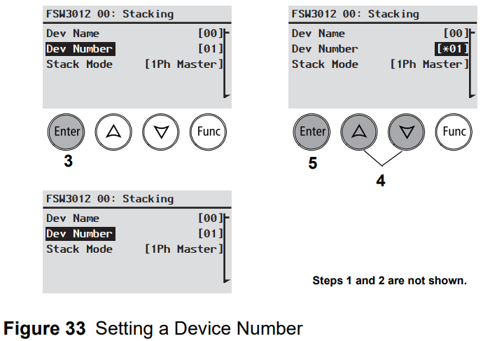
Setting the Device Number
Setting the device number gives a Xanbus-enabled device a unique identity when several devices of the same type are installed in the power system network. When each identical device has a unique number, the Xanbus SCP can correctly identify and display status information for each device. A device number consists of two digits ranging from 00 (default) to 31. If only one of each type of device is installed in the network, you do not need to set the device number. However, setting the device number to a value other than 00 is recommended in case you need to use the Restore Defaults command (which resets the device number to 00). After performing the command, checking that the device number has returned to 00 indicates that the command was successfully completed.
To set the Freedom SW device number:
- On the Freedom SW Setup menu, select Advanced Settings. If Basic Settings appears instead of Advanced Settings on the Setup menu, display Advanced Settings by pressing Enter + Up arrow + Down arrow simultaneously. On the Advanced Settings menu, select Stacking and press Enter.
- On the Stacking menu, select Dev Number.
- Press Enter to highlight the instance number.
- Use the Up and Down arrow buttons to adjust the two digit identifier number.
- Press Enter.
Cascading
The Cascading feature is found in the System Settings menu only when two inverters are configured as a stacked pair (see “Stacking Configuration Menu” on page 69). A stacked pair has one Master unit and one Slave unit. The cascading feature allows manually entered inverter/charger settings on the Master unit to be automatically cascaded (or copied) to the Slave unit when the two units are meant to have the same settings. Cascading helps simplify the duplication of settings of one inverter into another. The feature is Enabled by default but may be Disabled to accommodate different settings for the Master and Slave units. Review with a qualified system designer before adopting different settings for the Master and Slave units.
To change Cascading settings:
- From the System Status screen, press the Enter button. The Select Device menu screen appears.
- From the Select Device screen, press the Enter button. The System Settings menu screen appears.
- From the System Settings screen, press the Down arrow button to highlight Cascading.
- Press Enter and use the Up and Down arrow buttons to change selections.
- Press Enter again to choose a selection.
- Press Func (3x) to return to the System Settings menu.

Resetting the Freedom SW to Default Settings
The Restore Defaults command returns the Freedom SW to factory default settings. After using the Restore Defaults command, the Freedom SW is no longer configured for the power system. To restore Freedom SW default settings:
- On the Adv Settings menu, select Restore Defaults. Warning W252 appears, asking to confirm the command.
- To cancel the command, press Func. To continue with the Restore Defaults command, press Enter.
Using the Advanced Features

| Table 18 Adv Features Description and Values |
| Item | Description | Default | Range |
|
StoreInvState This feature is available only to Freedom SW 2024 (PN: 815-2024) |
When enabled remembers the state of the inverter function prior to a power down (that is, when AC and DC power sources are disconnected) or prior to a Standby (Power Save) mode. When the Freedom SW is powered up again or put back on Operating mode, the inverter function reverts back to its prior state. | Disabled | Disabled , Enabled |
Configuring the Freedom SW using the SCP
To store the state of the inverter to memory:
- Press and hold the STBY/ON Fault Clear button on the SCP for more than five seconds to switch to Standby (Power Save) mode.
- Select Advanced Settings on the SCP. See “To select the Advanced Settings menu screen:”
- On the Advanced Settings menu, select Adv Features.
- On the Advanced Features menu, select StoreInvState.
- Press Enter and use the Up and Down arrow buttons to change the setting to Enabled.
- Press Enter again to choose the selection.
- Press Func until you return to the System Status screen.
- Press and hold the STBY/ON Fault Clear button on the SCP for more than five seconds to switch back to Operating mode.
Battery Charging Reference
Battery Types
Freedom SW charges flooded (or wet) lead-acid, Gel, AGM (absorbed glass mat), and custom batteries.
- Flooded (or wet) batteries have removable battery caps for refilling with distilled water and testing the electrolyte.
- Gel batteries have the electrolyte in the form of a gel rather than a liquid and do not require topping up. Gel batteries are sealed and the battery caps are not removable.
- AGM (Absorbed Glass Mat) batteries are similar to gel batteries except that the electrolyte is absorbed into a fiberglass matting.
- Custom battery is configured by the dealer, factory, or service center for battery types other than those listed above.
Charge Algorithm Stages
Three-Stage charging
If three-stage charging is enabled, the Freedom SW will charge batteries in a sequence known as three-stage charging. Whenever qualified AC power is present at the inverter’s input, it passes power through to the connected load and begins charging the batteries. The charging voltage delivered to the battery depends on the battery’s:
- Type setting
- Temperature (by switch setting or battery temperature sensor)
- State of charge
The three automatic stages are:
- Bulk
- Absorption
- Float
See Figure 35 for a graph of the three-stage charging profile. There is a fourth stage, equalization, which is initialized manually as it is only performed occasionally and only on flooded (or wet) batteries.
The charging cycle is a multistage (three-stage) process. Whenever qualified AC power is present at the inverter’s input, it passes power through to the connected load and begins charging the batteries.

Bulk Stage
Bulk charge is the first stage in the charging process and provides the batteries with a controlled, constant current. Once the battery voltage rises to the absorption voltage threshold, the charger switches to the absorption stage.
| Table 19 Preset Bulk Voltage Settings |
| Termination Voltage | Preset Bulk Voltage | |||
| Battery Type | 12V models | 24V models | 12V models | 24V models |
| Flooded | 14.2 | 28.4 | 14.4 | 28.8 |
| Gel | 14.0 | 28.0 | 14.2 | 28.4 |
| AGM | 14.1 | 28.2 | 14.3 | 28.6 |
| Custom | 14.4 (changeable) | 28.8 (changeable) | 14.4 (changeable) | 28.8 (changeable) |
Absorption Stage
Absorption charge is the second stage of battery charging and provides the batteries with a controlled, constant voltage. During this stage, the current drawn by the batteries slowly decreases. When this current falls below 2% of the battery capacity, or when the configurable Absorb Time expires, the charger switches to the Float or NoFloat stage, depending on the selected charge cycle. The timer begins when the battery voltage is above the bulk termination voltage for three minutes.
| Table 20 Preset Absorption Voltage Settings |
| Preset Absorption Voltage | ||
| Battery Type | 12V Models | 24V Models |
| Flooded | 14.4 | 28.8 |
| Gel | 14.2 | 28.4 |
| AGM | 14.3 | 28.6 |
| Custom | 14.4 (changeable) | 28.8 (changeable) |
The Freedom SW transitions to the float stage if either one of the following two conditions are met:
- The charge current allowed by the batteries falls below the exit current threshold, which is equal to 2% of the programmed battery capacity (for a 500 amp-hour battery bank, this would be 10 amps), for three minutes.
- The Freedom SW has been in absorption for the programmed maximum absorption time limit. The default is 3 hours, but the time limit is programmable from 1 minute to 8 hours.
Float Stage
Float charge maintains the batteries slightly above the self discharge voltage of the batteries. The charge current in float is the current necessary to maintain the batteries at the Float Voltage setting, limited only by the inverter's capability or other settings that limit the inverter's maximum charge rate. Float charging reduces battery gassing, minimizes watering requirements (for flooded batteries), and makes sure the batteries are in a constant state of readiness. When three-stage charging is selected, the charger automatically switches to the float stage after the batteries have received a bulk and absorption charge (see Figure 35). The batteries are maintained at the default float voltage level for the selected battery type or the voltage selected under Float Voltage on the Custom Battery Settings menu.
| Table 21 Preset Float Voltage Settings |
| Preset Float Voltage | ||
| Battery Type | 12V Models | 24V Models |
| Flooded | 13.5 | 27.0 |
| Gel | 13.8 | 27.6 |
| AGM | 13.4 | 26.8 |
| Custom | 13.5 (changeable) | 27.0 (changeable) |
Two-Stage Charging Process
Two-stage (or no float) mode differs from an ordinary three-stage charge mode in that it does not continuously maintain the battery at float voltage. Instead, the Freedom SW begins charging the battery in bulk mode whenever the battery voltage drops below the recharge level. While the battery voltage is above the recharge level the inverter’s AC transfer switch continues to pass power through from the utility grid to the loads, but does not actively charge the batteries. Two-stage mode increases efficiency of utility connected systems by reducing the amount of power consumed by the inverter and batteries compared to when the battery is continuously maintained at Float Voltage. This feature can extend the life of most batteries.

Equalize Charging
Many battery manufacturers recommend periodic equalize charging to counter cell charge imbalance and capacity-robbing electrolyte stratification. Equalizing helps to improve battery performance and lifespan by encouraging more of the battery material to become active. Battery equalization is a controlled overcharging method that mixes up stratified electrolyte and reactivates unused areas of the plate material. Periodic equalizing can help to regularly restore batteries to a full and healthy state of charge. Consult the battery manufacturer's recommendation for equalize charging settings. Sealed batteries should never be equalized. Consult the battery manufacturer for optimal charging procedures when using sealed batteries. When Equalize mode is enabled, the battery is charged from bulk to absorption, and then to the equalize phase. The Freedom SW will transition from the absorption phase to equalize if:
- the DC charge current is below 2% of the configured battery capacity (for example, 8.8A for 440Ah)
- the absorption time is exceeded (for example, 180 min)
After absorption, the maximum charge DC current is set to 10% of battery capacity (for example, 44A for 440Ah). See Figure 37. This constant current charge will continue until the voltage has increased to the equalize voltage at which point the battery will be regulated at the temperature-compensated equalize voltage. If the battery capacity is set to zero (Ah=0 effectively disables the exit current criteria for the absorption charge stage making the absorption stage defined by time only), the equalize charge current is fixed at maximum 100% of the charge rate. Equalization duration is fixed at one hour.
| Table 22 Preset Equalization Voltage Settings |
| Preset Equalization Voltage | ||
| Battery Type | 12V models | 24V models |
| Flooded | 16.0 | 32.0 |
| Gel | n/a | n/a |
| AGM | n/a | n/a |
| Custom | 16.0 (changeable) | 32.0 (changeable) |

Troubleshooting
General Troubleshooting Guidelines
This section will help you narrow down the source of any problem you may encounter. Please read the following troubleshooting steps:
- Check for a warning or fault message on the Xanbus SCP or a fault code on the inverter information panel. If a message is displayed, record it immediately.
- As soon as possible, record the conditions at the time the problem occurred. These details should include the following information:
- Loads the Freedom SW was running or attempting to run
- Battery condition at the time of failure (battery voltage or temperature, for example), if known
- Recent sequence of events (for example, charging had just finished, utility grid had failed but the inverter did not come on)
- Any known unusual AC input factors such as low voltage or unstable generator output
- Extreme conditions which may have existed at the time (temperature or moisture, for example).
- Attempt the solution indicated in these guidelines.
- If your inverter information panel or Xanbus SCP is not displaying a Fault LED, check the following list to make sure that the present state of the installation allows proper operation of the unit. Read these guidelines carefully.
- Is the Freedom SW located in a clean, dry, adequately ventilated area?
- Have the AC input breakers opened? If so, your passthrough load may have exceeded the rating of one or more of the input breakers.
- Are the battery cables adequately sized and short enough? See the Installation Guide for more information.
- Is the battery in good condition and are all DC connections tight?
- Are the AC input and output connections and wiring in good condition?
- Are the configuration settings correct for your particular installation?
- Are the display panel and the communications cable properly connected and undamaged?
- Is the battery temperature sensor and its cable properly connected and undamaged?
- Contact Customer Service for further assistance. Please be prepared to describe details of your system installation and provide the model and serial number of the unit. See the front and/or back of the manual for contact information.
Inverter Applications
The Freedom SW performs differently depending on the AC loads connected to it. If you are having problems with any of your loads, read this section.
Resistive Loads
Resistive loads are the easiest and most efficient to drive. Voltage and current are in phase, which means they are in step with one another. Resistive loads generate heat in order to accomplish their tasks. Toasters, coffee pots, and incandescent lights are typical resistive loads. It is usually impractical to run larger resistive loads—such as electric stoves and water heaters—from an inverter due to their high current requirements. Even though the inverter may be able to accommodate the load, the size of battery bank will limit inverter run time.
Motor Loads
Induction motors (AC motors without brushes) require up to six times their running current on startup. The most demanding are those that start under load (for example, compressors and pumps). Of the capacitor start motors (typical in drill presses and band saws, for example), the largest you can expect to run is one horsepower. Universal motors are generally easier to start. Check that the Locked Rotor Amps (LRA) rating of the motor load does not exceed the maximum surge current rating of the inverter. Since motor characteristics vary, only testing will determine whether a specific load can be started and how long it can be run. If a motor fails to start within a few seconds or loses power after running for a time, it should be turned off. When the inverter attempts to start a load that is greater than it can handle, the inverter may shut down from an AC overload fault.
Problem Loads
Very Small Loads If the power consumed by a device is less than the threshold of the search mode circuitry, and search mode is enabled, the inverter will not run. Most likely the solution will be to disable Search mode or lower the sense threshold.
Fluorescent Lights and Power Supplies
- Some devices cannot be detected when scanned by search mode circuitry. Small fluorescent lights are the most common example. Some computers and sophisticated electronics have power supplies that do not present a load until line voltage is available. When this occurs, each unit waits for the other to begin. To drive these loads, either a small companion load like a light bulb rated for more than the Search Watts setting must be used to bring the inverter out of search mode, or the inverter may be programmed to remain on by disabling Search mode. (See “Using Search Mode” on page 45.)
Clocks
- You may notice that your clocks are not accurate. Some of the clocks on your appliances may reset when the Freedom SW is in search mode.
Searching
- When the inverter is in search mode, it may fail to start some loads even though the rated wattage on the load is more than the Search Watts setting. Disable Search or apply an additional load (companion load) to make the inverter exit search mode.
Troubleshooting the Freedom SW via the SCP
The Freedom SW is designed with a number of protection features to provide efficient operation. If, however, you have any problems operating your inverter/charger read this troubleshooting chapter. If you cannot resolve the problem, record the information about your system. This information will help your dealer or customer service to assist you better when you contact them.
When a detected fault or warning message appears, you can acknowledge the message to clear the screen. To acknowledge a fault or warning message, press the Enter button on the SCP. This action does not clear the fault or warning condition, so you should consult “Detected Fault Messages” and “Detected Warning Messages” for suggested actions after you have acknowledged the message. Refer to the Xanbus System Control Panel Owner’s Guide for more information on detected faults and warnings.
Detected Fault Types
There are three types of detected fault messages: automatic faults, manual faults, and escalating automatic faults. Table 1 describes how they differ in their behavior and how you can respond to them when they appear on the SCP.
| Table 1 Detected Fault Types and Behaviors |
| Fault Type | Behavior |
| Automatic fault | Clears automatically if the detected condition that generated the message goes away. You can also acknowledge automatic faults without waiting for them to clear automatically. |
| Manual fault |
Requires you to clear it by:
|
| Escalating automatic faults |
Clears automatically if the detected fault condition goes away, just like an automatic fault. However, if an escalating automatic fault occurs several times within a defined time period, the escalating automatic fault becomes a manual fault, requiring user intervention. For example, if three detected faults occur in one minute, it will no longer clear itself but becomes a manual fault. Then, you must identify the problem, correct the condition that detected the fault, and clear the fault or reset the device. |
To view a fault list:
- On the Select Device menu, highlight System and press Enter.
- On the System Settings menu, highlight View Fault List.
- Press Enter.
Detected Warning Types
There are two types of detected warnings: automatic and manual. When the Freedom SW detects a warning condition, it displays a warning message on the SCP. Table 2 describes how they differ in their behavior and in how you can respond to them when they appear on the SCP.
To view a warning list:
- On the Select Device menu, highlight System and press Enter.
- On the System Settings menu, highlight View Warning List.
- Press Enter.
| Table 2 Detected Warning Types and Behavior |
| Warning type | Behavior |
| Automatic warning | Clears automatically if the detected condition that generated the message goes away. You can also acknowledge automatic warnings without waiting for them to clear automatically. |
| Manual warning | Requires you to acknowledge it before you can proceed with configuring or operating the Freedom SW. Manual warnings are usually in the form of a Yes/No question that you may acknowledge by pressing the Enter button on the SCP for Yes and the Func button for No. |
| Table 3 Detected Fault Messages |
| Fault Number | Message | Fault Type | Cause | Solution |
| F1 | AC Output under voltage | Escalating Auto Fault. Must occur 3 times in 30 seconds before becoming a manual fault. | Inverter voltage is under 100 volts. | Remove excessive load. |
| F2 | AC Output over voltage | Escalating Auto Fault. Must occur 3 times in 30 seconds before becoming a manual fault. | Inverter voltage is over 135 volts. | Check if there is an external power source that is running parallel to the inverter’s output. |
| F17 | Relays Welded | Manual | AC backfeed from welded relay. | Service required. |
| F18 | ||||
| F44 | Battery Over Temperature | Automatic | Battery temperature is over 140 °F (60 °C). Poor battery compartment ventilation. | Stop charging if necessary. Check cable connections. Check battery voltage/current and temperature. If battery is not accepting charge, it may need to be replaced. Check for excessive ambient temperature and adequate ventilation in the battery compartment. |
| Automatic | BTS may be damaged. | If the unit displays a temperature of over 212 °F (100 °C), the BTS will need to be replaced. | ||
| F46 | Controller Error | Manual | Unit’s control board may be damaged. | Service is required. |
| F47 | DC Under Voltage (Immediate) | Automatic | Immediate battery under voltage fault. | Check battery condition (short or open cells) and ensure correct voltage. Battery state charge or capacity is so low that the DC voltage collapses when inverter load is applied. Inverter load is so large that the DC voltage collapses when inverter load is applied. |
| F48 | DC Under Voltage (Fault) | Automatic | Voltage at the DC input terminals is below the Low Battery Cut Out (LBCO) setting for 10 seconds. | Check for the correct battery voltage at the inverter's DC input terminals. Check for external DC loads on the batteries. Check condition of batteries and recharge if necessary. Reduce the Low Battery Cut Out (LBCO) setting. Battery bank capacity may be inadequate for the loads in the system. |
| F49 | DC Over Voltage | Automatic | Voltage at the DC input terminals is above the High Battery Cut Out Setting | Clear the fault and attempt restart. Ensure battery voltage is 10–16 VDC at Freedom SW terminals. Check all other charging source outputs, battery cables. |
| F52-F56 | EEPROM ERROR | Manual | A problem has been detected with the internal memory. | Clear the fault and check the latest configuration made or any recent configurations. If fault detection reoccurs or occurs frequently, service is required. |
| F57 | FET1 Over Temperature | Automatic | Ambient temperature may be too high. | Ensure adequate ventilation around the Freedom SW. Allow inverter to cool down and try restarting. |
| Operating too large of a load for too long while inverting. | Remove excessive inverter loads. | |||
| Inverter cooling fan may have failed. | If the temperature is above 104 °F (40 °C), the fan should be on. Hold your hand or a piece of paper to the inverter vent to check if the fan is working. Both fans should be active at the same time. | |||
| Inverter airflow intake may be blocked. | Increase the clearance around the inverter and/or unclog the airflow intake vents. | |||
| F58 | FET2 Over Temperature | Automatic | Same as F57. | Same as F57. |
| F59 | GOCFG process failed | Manual | The unit may be running outdated firmware. | Clear the fault and check if the latest firmware is installed. If not, download and install the latest firmware from the website. |
| F62 | Invalid Interrupt | Manual | Unit’s control board may be damaged. | Service is required. |
| F63 | Power Board Temp unreadable | Automatic | Temperature sensor is damaged. | Service required. |
| F64 | AC overload | Escalating Auto Fault. Must occur 3 times in 60 seconds before becoming a manual fault. | Persistent excessive inverter current above rated current. | Avoid loads with long surge current. |
| F67 | Watchdog Error | Manual | Unit’s control board may be damaged. | Service is required. |
| F68 | Transformer Over Temperature | Automatic | Same as F57. | Same as F57. |
| F69 | External Sync Failed | Automatic | When Series stacking— the Stacking cable is not installed. | Install the Stacking cable to connect the two inverter/chargers. |
| F70 | Unique Dev# Needed | Automatic | When stacking (Series or Parallel)—if two units have the same Device Number. | Change the Device Number of one unit. See “Setting the Device Number”. |
| F71 | Too Many Masters | Automatic | When stacking (Series or Parallel)—if two units are configured as Master units. | Change one unit to a Slave unit. See Stack Mode under “Stacking Configuration Menu” |
| F73 | Transformer Temp unreadable | Automatic | Temperature sensor is damaged. | Service required. |
| F74 | Other Unit Invert Fault | Automatic | When stacking (Series or Parallel)—if one of the units encounters a fault that needs to be resolved. | Clear the primary fault on the unit that caused this fault. |
| F75 | Master Inverter Lost | Automatic | When Parallel stacking—if the Slave unit cannot detect the Master unit in the Xanbus network. | Make sure that the two units are connected in the same Xanbus network. Check cable connections and ensure that the plugs are neatly inserted in the ports. Check if the Xanbus network is properly installed with network terminators. |
| F76 | No Masters | Automatic | When stacking (Series or Parallel)—if all units are configured as Slave. | Assign the other unit as Master. |
| F77 | ||||
| F79 | Battery Sensor Short | Automatic | The BTS has been damaged. | Replace the BTS. |
| F85 | PowerBoard Over Temperature | Automatic | Same as F57. | Same as F57. |
| F86 | Dead Battery Detected | Automatic | When battery voltage is below the allowable charging voltage. | Recharge the battery with an external charging device. If the error persists, then the battery may be defective. Replace the battery. |
| F88 | MPPT Ground Fault | Automatic | In a Xanbus network, an MPPT has detected a ground fault (MPPT generated code F56). | Check the MPPT and correct the ground fault. |
| Table 4 Detected Warning Messages |
| Fault Number | Message | Cause | Solution |
| W48 | DC under voltage (Warning) | Voltage at the DC input terminals is below the Low Battery Cut Out (LBCO) setting. | Check for the correct battery voltage at the inverter's DC input terminals. Check for external DC loads on the batteries. Check condition of batteries and recharge if necessary. Reduce the Low Battery Cut Out (LBCO) setting. Battery bank capacity may be inadequate for the loads in the system. |
| W72 | AC Out Assoc Mismatched | In a stacking configuration— the AC In settings are not the same for both units. | Change the AC In setting of both units in the stacking configuration to be the same. See “Stacking Configuration Menu” |
| W87 | Inconsistent Frequencies | In a stacking configuration— the AC input low and high frequency settings are not the same for both units. | Change the AC input low and hi frequency settings of both units in the stacking configuration to be the same. See “ACIn Settings” |
| W92 | Input Connected to 3-Phase AC |