Magnum Pure Sine Wave Installation Instructions
Installation
Info: Installations should be performed by qualified personnel, such as a licensed or certified electrician. It is the installer’s responsibility to determine which safety codes apply and to ensure that all applicable installation requirements are followed. Applicable installation codes vary depending on the specific location and application of the installation.
CAUTION: The inverter is heavy. Use proper lifting techniques during installation to prevent personal injury
The simplified system diagram shown in Figure 2-1 should be reviewed to assist you in planning and designing your installation. This drawing is not intended to override or restrict any national or local electrical codes. This drawing should not be the determining factor as to whether the installation is compliant, that is the responsibility of the electrician and the on-site inspector.
Pre-Installation
Before proceeding, read the entire Installation section to determine how best to install your MS inverter/charger. The more thorough you plan in the beginning, the better your inverter needs will be met.
Unpacking and Inspection
Carefully remove the MS Series inverter/charger from its shipping container and inspect all contents. Verify the following items are included:
- The MS inverter/charger
- Red and black DC terminal covers with Phillips screws
- AC access cover with two Phillips screws
- Two 5/16” Kep or Flange nuts (installed on the DC terminals)
- Battery Temperature Sensor
- Warning label
- MS Series owner’s manual
If items appear to be missing or damaged, contact your authorized Magnum Energy dealer or Magnum Energy. If at all possible, keep your shipping box to help protect your inverter from damage if it ever needs to be returned for service. Save your proof-of-purchase as a record of your ownership; it will also be needed if the unit should require in-warranty service.
Record the unit’s model and serial number in the front of this manual in case you need to provide this information in the future. It is much easier to record this information now, instead of trying to gather it after the unit has been installed.
Required Tools and Materials
Hardware/Materials
- Conduit, strain-reliefs and appropriate fittings
- 1/4” mounting bolts and lock washers
- Electrical tape
- Wire ties
Tools
- Miscellaneous screwdrivers
- Pliers
- Wire strippers
- Drill and drill bits
- Pencil or marker
- Multimeter
- Level
- 1/2” wrench

Locating the Inverter
Only install the inverter in a location that meets the following requirements:
Clean and Dry – The inverter should not be installed in an area that allows dust, fumes, insects, or rodents to enter or block the inverter’s ventilation openings. This area also must be free from any risk of condensation, water, or any other liquid that can enter or fall on the inverter. The inverter uses stainless steel fasteners, plated copper busbars, a powder-coated aluminum base and the internal circuit boards are conformal coated – to help fight the harmful effects of corrosive environments. However, the inverter’s life is uncertain if used in these type of environments, and inverter failure under these conditions is not covered under warranty.
Cool – The inverter should be protected from direct sun exposure or equipment that produces extreme heat. The ambient temperature around the inverter must not exceed 77°F (25°C) to meet power specifications.
Ventilation – In order for the inverter to provide full output power and to avoid over-temperature fault conditions, do not cover or block the inverter’s ventilation openings or install this inverter in an area with limited airflow. The inverter uses two fans to provide forced air cooling, these fans pull in air through the intake vents (see Item 9, Figure 1-2) and blow out air through the exhaust vents (see Item 13, Figure 1-3). Allow at the minimum an airspace clearance of 6” at the intake and exhaust vents, and 3” everywhere else to provide adequate ventilation. If installed in an enclosure, a fresh air intake opening must be provided directly to the front side (intake vents) of the inverter and an exhaust opening on the back side (exhaust vents) of the inverter. This allows cool air from the outside to fl ow into the inverter and heated air to exit the inverter and the enclosure. When mounted in an enclosed compartment, airflow must be ≥ 100 cfm in order to maintain no more than a 68°F (20°C) rise in compartment temperature.
Safe – Keep any flammable/combustible material (i.e., paper, cloth, plastic, etc.) that may be ignited by heat, sparks, or flames at a minimum distance of 2 feet away from the inverter. Do not install this inverter in any area that contains extremely flammable liquids like gasoline or propane, or in locations that require ignition-protected devices.
Close to the battery bank – As with any inverter, it should be located as close to the batteries as possible. Long DC wires tend to lose efficiency and reduce the overall performance of an inverter. However, the unit should not be installed in the same compartment as the batteries or mounted where it will be exposed to gases produced by the batteries. These gases are corrosive and will damage the inverter; also, if these gases are not ventilated and allowed to collect, they could ignite and cause an explosion.
Accessible – Do not block access to the inverter’s remote control and accessory ports, as well as the inverter’s controls and status indicator. Allow enough room to access the AC and DC wiring terminals and connections, as they will need to be checked and tightened periodically. See Figure 2-3 for the MS Series inverter/charger’s dimensions.
Away from sensitive electronic equipment – High powered inverters can generate levels of RFI (Radio Frequency Interference). Locate any electronic equipment susceptible to radio frequency and electromagnetic interference as far away from the inverter as possible.
Mounting the Inverter
The inverter base can reach a temperature up to 90°C (194°F) and should be mounted on a noncombustible surface. This surface and the mounting hardware must also be capable of supporting at least twice the weight of the inverter. To meet regulatory requirements, the MS Series must be mounted in one of the following positions as shown in Figure 2-2:
- above or under a horizontal surface (shelf or table),
- on a vertical surface (wall) with the DC terminals to the right,
- on a vertical surface (wall) with the DC terminals toward the bottom, the MP-HOOD (inverter hood) installed on the top, and either the ME-CB (Conduit box), MMP series (single inverter enclosure), or MP Series (multiple inverter enclosure) installed on the inverter’s bottom.
After determining the mounting position, refer to the physical dimensions as shown in Figure 2-3, or use the base of the inverter as a template to mark your mounting screw locations. After marking the mounting screw locations, mount the unit with appropriate mounting hardware.


Wiring the Inverter - General Requirements
This section describes the requirements and recommendations for wiring the MS Series inverter/ charger. Before wiring the MS Series inverter/charger, carefully read all instructions.
Wiring should meet all local codes and standards and be performed by qualified personnel such as a licensed electrician.
The NEC (National Electric Code, ANSI/NFPA 70) for the United States and the CEC (Canadian Electrical Code) for Canada provide the standards for safely wiring residential and commercial installations. The NEC/CEC lists the requirement for wire sizes, overcurrent protection, and installation methods and requirements. Inverter/charger systems involve power from multiple sources (inverter, generator, utility, batteries, solar arrays, etc.) which make the wiring more hazardous and challenging. The input and output AC and DC circuits are isolated from the inverter chassis. The inverter system grounding is the responsibility of the installer in accordance with the NEC/CEC.
Protecting Wire – Conduit Box
The AC and DC wires to and from the inverter must be protected as required by code. This can be done by using jacketed wires or by feeding the wires through conduit. Magnum offers a DC conduit box (ME-CB), a single inverter enclosure (MMP Series), and a multiple inverter enclosure (MP Series) that include the necessary AC and DC inverter breakers that allow both the AC and DC conduit to be connected to the inverter.
Wiring Requirements
- All conductors that are at risk for physical damage must be protected by conduit, tape, or placed in a raceway.
- Always check for existing electrical, plumbing, or other areas of potential damage prior to making cuts in structural surfaces or walls.
- Do not mix AC and DC wiring in the same conduit or panel unless specifically approved/ designed for both AC and DC wiring. Where DC wiring must cross AC or vice-versa, try to make the wires at the crossing point perpendicular (90 degrees) to one another.
- Both AC and DC overcurrent protection must be provided as part of the installation.
- The inverter requires a reliable negative and ground return path directly to the battery.
- Use only copper wires with a minimum temperature rating of 90°C.
Wire Routing
Before connecting any wires, determine all wire routes to and from the inverter. Typical routing scenarios are:
- AC input wiring from the main AC panel to the inverter.
- AC input wiring from a generator (optional) to the inverter.
- DC input wiring from the batteries to the inverter.
- AC output wiring from the inverter to the AC sub-panel or to dedicated circuits.
- Battery Temperature Sensor cable from the inverter to the batteries.
- Remote control cable (optional) to the inverter.
- Ground wiring to and from the inverter.
Torque Requirements
Torque all AC wiring connections to 16 in lbf (1.8 N-m). Torque DC cable connections from 10 to 12 ft lbf (13.6 to 16.3 N-m).
DC Wiring
This section describes the inverter’s required DC wire sizes, the recommended disconnect/overcurrent protection, and how to make the DC connections to the inverter and the battery bank. Refer to Figure 2-4 when connecting the DC wires.
- When the inverter is installed in a Photovoltaic System, the NEC requires that the DC circuit conductors and overcurrent devices to the inverter be sized to carry not less than 125% of the inverter’s maximum current rating.
- The DC positive and negative cables connected to the inverter from the battery bank should be tied together with wire ties or electrical tape approximately every 6 inches. This helps improve the surge capability and reduces the effects of inductance, which improves the inverter waveform and reduces the wear of the inverter’s filter capacitors.
- Crimped and sealed copper ring terminal lugs with a 5/16” hole should be used to connect the DC wires to the inverter’s DC terminals.
- The battery bank voltage MUST match the DC voltage required by the inverter (i.e., 24-volt battery bank for a 24-volt inverter) or the inverter may be damaged.
- To ensure the maximum performance from the inverter, all connections from the battery bank to the inverter should be minimized. The exception is the DC overcurrent disconnect in the positive line and a shunt in the negative line. Any other additional connection will contribute to additional voltage drops, and these extra connection points may loosen during use.
- All wiring to the battery terminals should be checked periodically (once a month) for proper tightness. The torque requirement for the DC terminals is between 10 to 12 ft lbf (13.6 to 16.3 N-m). If you don’t have a torque wrench, ensure all DC terminals are tight and cannot move.
- Be aware that overtightening or misthreading the nuts on the DC terminals can cause the bolts to strip and snap/break off.
- Make sure cables have a smooth bend radius and do not become kinked. Place long cable runs in conduit and follow existing wire runs where possible.
- A brief spark or arc may occur when connecting the battery cables to the inverter DC terminals; this is normal and due to the inverter’s internal capacitors being charged.
- Color code the DC cables/wires with colored tape or heat shrink tubing: RED for positive (+); WHITE for negative (-); and GREEN for DC ground, to avoid polarity problems.

DC Wire Sizing
It is important to use the correct sized DC wire to achieve maximum efficiency from the system and to reduce fi re hazards associated with overheating. Always keep your wire runs as short as practical to prevent low voltage shutdowns and to keep the DC breaker from nuisance tripping (or open fuses) because of increased current draw. See Table 2-1 to select the minimum DC wire size (and corresponding overcurrent device) required based on your inverter model. The cable sizes listed in Table 2-1 are required in order to reduce stress on the inverter, minimize voltage drops, increase system efficiency, and ensure the inverter’s ability to surge heavy loads. If the distance from the inverter to the battery bank is >5 feet, the DC wire will need to be increased. Longer distances cause an increase in resistance, which affects the performance of the inverter. Use the overcurrent device previously determined from Table 2-1 and then refer to Table 2-2 to determine the minimum DC wire size needed for various distances, based on your inverter model.
DC Overcurrent Protection
DC overcurrent protection is not included in the inverter—for safety reasons and to comply with electrical code regulations—it must be provided as part of the installation. The DC overcurrent protection device must be installed in the positive DC cable line, it can be a fuse or a circuit breaker and must be DC rated. It must be correctly sized according to the size of DC cables being used, which means it is required to open before the cable reaches its maximum current carrying capability, thereby preventing a fire. In a residential or commercial electrical installation, the NEC requires both overcurrent protection and a disconnect switch. If a circuit breaker is used as the overcurrent protection device, it can also be used as the required DC disconnect.
If a fuse is used as an overcurrent device, a Class-T type or equivalent is recommended. This fuse type is rated for DC operation, can handle the high short-circuit currents and has a time delay that allows for momentary current surges from the inverter without opening the fuse. However, because the fuse can be energized from both directions, if it is accessible to unqualifi ed persons, the NEC requires that it be installed in a manner that the power must be disconnected on both ends of the fuse before servicing. Use Table 2-1 to select the DC overcurrent device needed based on the recommended minimum wire size for your particular inverter model (may not meet all local code or NEC requirements).


DC Cable Connections
Do not put anything between the battery cable ring lug and the battery post or the fl at metal part of the inverter’s DC terminal. When connecting the battery cable to the battery post or inverter DC terminal, the cable should be placed directly against the inverter terminal or battery post. Incorrectly installed hardware causes a high resistance connection which could lead to poor inverter/ charger performance, and may melt the cable and terminal connections. Refer to Figures 2-5 and 2-6 to connect the DC cables and to stack the hardware correctly. Tighten the terminal connections from 10 to 12 ft lbf (13.6 to 16.3 N-m).

Wiring the DC Overcurrent Protection Device
A fuse/disconnect or circuit breaker must be provided in the DC positive line between the battery and the inverter to protect the DC wiring system. Mount the fuse block (or circuit breaker assembly) as near as practical to the batteries. For maximum protection, install it within 18 inches (45 cm) of the battery.
- Open the fuse disconnect (or open the circuit breaker) and connect a short cable (same rating as the battery cables) to one end of the fuse block.
- Connect the short cable to the positive battery terminal.
- Connect the positive cable (RED) from the inverter to the fuse/disconnect (or circuit breaker) assembly. DO NOT connect the positive cable to the inverter at this time.
- Securely tighten the fuse/disconnect (or circuit breaker) connection lugs. Once the entire installation is complete and all connections are verified, close the fuse disconnect (or circuit breaker) to provide power to the inverter.
Wiring the Battery Bank
Depending upon the voltage of the batteries you use in the installation (6 or 12 VDC), the batteries must be wired in series, parallel, or series-parallel to provide the correct voltage (see Appendix B - Battery Information for guidance on wiring batteries together). The interconnecting DC wires must be sized and rated exactly the same as those used between the battery bank and the inverter.
Place the batteries as close as practical to the inverter, preferably in an insulated and ventilated enclosure. Allow adequate space above the batteries to access the terminals and vent caps (as applicable). Also, allow at least 1” of space between the batteries to provide good air fl ow. DO NOT mount the batteries directly under the inverter.
Battery Temperature Sensor Installation and Wiring
The Battery Temperature Sensor (shown in Figure 2-7) provides the inverter with precise battery temperature information to automatically adjust the ABSORB and FLOAT charge voltage set-points. This allows the batteries to be correctly charged under extreme temperature changes. If the temperature sensor is NOT installed and the batteries are subjected to large temperature changes, the batteries’ lives may be shortened. The BTS cable may be extended—using a RJ11 connector (female to female) and a standard phone cable with RJ11 connectors—to a maximum length of 40 feet. However, your inverter to battery cable length should not exceed the recommended distance provided in Table 2-2.
To install the BTS:
- Attach the ring terminal end of the Battery Temperature Sensor to the negative battery terminal; see Figure 2-5 for proper connection to the battery terminal.
- Route the sensor’s cable to the inverter following existing wire runs.
- Connect the RJ11 connector end of the BTS cable to the yellow-labeled BTS port on the inverter (Item 6, Figure 1-1).

Wiring the Inverter to the Battery Bank
DC Ground Wire: Route an appropriately sized DC grounding wire (green or bare wire) from the inverter’s DC equipment ground terminal (Item 7, Figure 1-2) to a dedicated system ground. Recommended tightening torque is 45 in lbf (5.1 N-m). Refer to Section 2.6 for grounding information and sizing the DC ground wires.
DC Negative Wire: Route an appropriately sized DC negative wire (marked white) from the negative terminal of the battery bank to the inverter’s negative terminal (Item 11, Figure 1-2).
DC Positive Wire: Mount the circuit breaker or fuse assembly as near as practical to the batteries and leave open (i.e., no power to inverter).
Route and connect an appropriately sized DC positive wire (red) from the inverter’s positive DC terminal (Item 10, Figure 1-2) to one end of circuit breaker (or DC fuse block). Connect a short wire (same rating as the DC wires) to the other side of the DC circuit breaker (or one end of the fuse/disconnect assembly) and the other end of the short wire to the positive terminal of the battery bank (see Figure 2-1 for reference). This is essential to ensure even charging and discharging across the entire battery bank. Ensure the DC wire connections (on the batteries, inverter, and DC circuit breaker/fuse lugs) are fl ush on the surface of the DC terminals, and the hardware (lock washer and nut) used to hold these connections are stacked correctly (see Figures 2-5 and 2-6). Verify all DC connections are torqued from 10 to 12 ft lbf (13.6 to 16.3 N-m).
Once the DC connections are completely wired and tested, coat the terminals with an approved anti-oxidizing spray. Attach the red and black terminal covers over the inverter’s DC connectors and secure them in place with the supplied screws. If the batteries are in an enclosure, perform a fi nal check of the connections to the battery terminals, then close and secure the battery enclosure.
AC Wiring
This section provides information on how to make the AC connections to the inverter using the correct AC wire size and corresponding overcurrent protection.
Pre-AC Wiring Requirements
- Read all instructions and cautionary markings located at the beginning of this manual and in the pre-installation section before installing the inverter and batteries.
- Always use properly rated circuit breakers. If using an electrical sub-panel, circuit breakers can be moved from the main electrical panel to the sub-panel only if the breakers are also listed to be installed in the sub-panel.
- AC wiring must be no less than #10 AWG (5.3 mm2) gauge copper wire and be approved for the application (i.e., residential, RV, or marine wiring).
- DO NOT connect the inverter’s output to an AC power source. This could cause severe damage to the inverter and is not covered under warranty.
AC Wire Size and Overcurrent Protection
The AC input and output wiring must be sized per the local electrical safety code requirements to ensure the wire’s ability to safely handle the inverter’s maximum load current. The AC wiring must be protected from short circuits and overloads by an overcurrent protection device and have a means to disconnect the AC circuits. AC overcurrent protection is not included in the inverter and must be provided as part of the inverter installation. The AC overcurrent protection device must be a circuit breaker or a fuse/disconnect and be properly sized and branch circuit rated for the wire it is protecting and the appliances being powered.
The MS Series provides a terminal block (see Figure 2-8) that allows the AC input and output wiring to be permanently wired. This terminal block allows a service/distribution panel (main panel) to be wired to the inverter’s input, and a dedicated panel (sub-panel)1 between the inverter’s output wiring and the AC loads. These systems use the circuit breakers provided in the panels as the overcurrent protection and the AC disconnect device.
When in the Standby mode, the full AC continuous pass-thru capacity of the MS Series inverter/ charger is 30 amps for each AC leg² (AC HOT 1 and AC HOT 2). However, the AC HOT 1 and AC HOT 2 may be combined to obtain a 60-amp pass-thru capability (see Figure 2-10 for the SISO60A configuration). For a 30-amp continuous pass-thru capability, each AC HOT input to the inverter requires a 30-amp continuous duty rated breaker³, which corresponds to a minimum cable size of #10 AWG4 in conduit. When tying the AC HOT 1 and HOT 2 together for a 60-amp continuous pass-thru capability, the AC input to the inverter requires a 60 amp continuous duty rated breaker³, which corresponds to a minimum cable size of #6 AWG4 in conduit. If you are using other circuit breakers/wire sizes, refer to the appropriate electrical codes for proper sizing requirements.
Recommended GFCI (Ground Fault Circuit Interruption) Breakers
Some electrical safety codes require the use of GFCIs. In compliance with UL standards, Magnum Energy has tested the following GFCIs and fi nd that they function properly when connected to the inverter’s AC output:
- Shock SentryTM #XGF15V-SP
- Leviton Smart Lock #8899-A
- Hubbel #GF520EMBKA
AC Terminal Block Connections
The inverter has a six-pole AC terminal block and one AC ground terminal to connect the inverter’s AC input and output wiring. To access and view the AC terminal block and ground terminal, remove the two Phillips screws holding the AC wiring access cover plate (see Item 15, Figure 1-3).
Each connection on the AC terminal block is rated to accept one #14 to #6 AWG (2.1 to 13.3 mm2) CU stranded wire, or two #12 AWG (3.3 mm2) CU stranded wires. Each connection uses a M3.5 slotted head screw, and the maximum tightening torque is 16 lbf-in (1.8 N-m).
The AC ground terminal can accept one #14 to #6 AWG (2.1 to 13 mm2) CU stranded wire. It uses a slotted head screw and has a recommended maximum tightening torque of 45 in lbf (5.1 N-m). For multiple ground wires, use a pressure or mechanical connector to attach the single wire from the AC ground terminal to the input and output ground connections.

AC Conductor Wiring
The following steps are basic guidelines for installing and connecting the AC wiring to and from all MS Series inverters (except MS2000 Series model inverters – for instructions on wiring MS2000 Series model inverters, refer to Section 2.5.7). Before proceeding, refer to Table 2-3 to determine your AC wiring configurations.
Wiring the Inverter AC Input
- Remove the two Phillips screws on the AC wiring access cover (Item 15, Figure 1-3) to access the internal AC terminal block (see Figure 2-8).
- Route the cable from the AC electrical main panel through one of the strain relief clamps on the inverter (Item 8, Figure 1-2). Tighten the strain relief clamp securely on the cable. Always leave a little extra slack in the wiring.
- Connect the hot wire (BLACK) from the main panel’s dedicated breaker to the inverter’s AC HOT 1 IN terminal. Tighten the AC HOT 1 IN terminal to 16 in lbf (1.8 N-m).
- Connect the neutral (WHITE) from the main panel’s neutral busbar to the inverter’s AC NEUT IN terminal. Tighten the AC NEUT IN terminal to 16 in lbf (1.8 N-m).
Wiring the Inverter AC Output
- Route the cable through the unused strain relief clamp on the inverter (Item 8, Figure 1-2) to the AC electrical sub-panel (or outlets, if using the output breaker versions). Tighten the strain relief clamp securely on the cable.
- Connect the hot (BLACK) wire from the inverter’s AC HOT 1 OUT terminal to the sub-panel‘s main breaker (or to the hot connections on the outlets if using the output breaker versions). Tighten the AC HOT 1 OUT terminal to 16 in lbf (1.8 N-m).
- Connect the neutral (WHITE) from the inverter’s AC NEUT OUT terminal to the sub-panel’s neutral busbar (or to the neutral connection on the outlets if using the output breaker versions). Tighten the AC NEUT OUT terminal to 16 in lbf (1.8 N-m).
Wiring the Inverter AC Ground
- Combine the ground (GREEN) wire from the main panel’s ground busbar and the ground (GREEN) wire from the sub-panel’s ground busbar (or the ground connection on the outlets if using the output breaker versions). After these grounds are combined, connect them to the inverter’s AC GROUNDS terminal. Tighten the AC GROUNDS terminal to 16 in lbf (1.8 N-m).
AC Wiring Inspection
- Verify all cables runs are secured. If installed in a mobile installation, use wire ties or other non-conductive fasteners to prevent chafing or damage from movement and vibration.
- Verify strain reliefs or grommets are in place to prevent damage to the wiring or conduit where it passes through walls/bulkheads or other openings.
- After verifying all AC connections are correct and all inverter AC terminal screws are torqued to 16 in lbf (1.8 N-m), replace the AC wiring access cover and the covers on the main electrical/ distribution panel.
AC Wiring Configurations
The following table provides the different wiring configurations for installing and connecting the AC conductors to and from the inverter (refer to Figures 2-9 to 2-13 for installation drawings showing these configurations).
| Table 2-3, AC Input/Output Wiring Configurations |
| SI/SO (30A) Single In/ Single Out (30A) | SI/SO (60A) Single In/ Single Out (60A) | SI/DO Single In/ Dual Out | DI/SO Dual In/Single Out | DI/DO Dual In/ Dual Out | |
| AC Source Required | 120 VAC @ < 30 amps | 120 VAC @ > 30 amps (60 amps maximum) | 120/240 VAC (or 2 separate legs of 120 VAC) @ < 15 amps per leg (-15B models); or < 20 amps per leg (-20B models). | 120/240 VAC (or 2 separate legs of 120 VAC) @ < 30 amps per leg | 120/240 VAC (or 2 separate legs of 120 VAC) @ < 30 amps per leg |
| Reason to Use | Have an 120 VAC source that is < 30 amps. Requires a separate inverter sub-panel. | Have an 120 VAC source that is > 30 amps. Requires a separate inverter sub-panel. | Do not want to install a separate inverter sub-panel. Inverter pass-thru capability limited by model used: -15B = 30 amps; -20B = 40 amps. | Want dedicated charging and dedicated passthru while the AC source is on. Requires a separate inverter sub-panel. | May need to power 240 VAC loads when AC source is on (requires 120/240 VAC source). Requires a separate inverter sub-panel. |
| Appropriate Models |
MS2012 MS2812 MS4024 |
MS2012 MS2812 MS4024 |
MS2012-20B MS2012-15B |
MS2012 MS2812 MS4024 |
MS2012 MS2812 MS4024 |
| Maximum Input Breaker Required - Minimum Wire Size |
30A (single pole) - #10 AWG (In & Out) |
60A (single pole) - #6 AWG (In & Out); Can be split to two #10 AWG (for HOT 1 & HOT 2) |
-15B models: 30A (single pole); -20B models: 40A (single pole) - #10 AWG (In) (Hot input must be split to two #12 AWG); #12 AWG x2 (Out) |
30A (dual pole) - #10 AWG (In & Out) |
30A (dual pole) - #10 AWG (In & Out) |
| Maximum Inverter Pass-thru capacity |
3600W (30A @ 120 VAC) |
7200W (60A @ 120 VAC) |
-15B models: 3600W (30A @ 120 VAC) -20B models: 4800W (40A @ 120VAC) |
3600W (30A @ 120 VAC) |
7200W (2 legs of 30A @ 120/240 VAC or 2 legs of 30A @ 120 VAC)2 |
| Wiring Diagram | Figure 2-9 | Figure 2-10 | Figure 2-11 | Figure 2-12 | Figure 2-13 |


AC Conductor Wiring (MS2000 models)
The MS2000 offers a cost-effective alternative to the MS2012 while still providing the same features. This model has a slightly smaller height, but otherwise has the same footprint as the other MS Series inverters. The MS2000 can be wired in a single in - single out configuration, as well as a single in - dual out configuration (-15B & -20B). The following steps are basic guidelines for installing and connecting the AC wiring into and out of the inverter. Refer to Table 2-4 to determine your AC wiring configurations before beginning.
Wiring the Inverter AC Input
- Remove the two Phillips screws on the AC access cover (Item 15, Figure 1-3) to access the internal AC wiring.
- Route the cable from the AC electrical main panel through one of the strain relief clamps to the AC INPUT. Tighten the strain relief clamp securely on the cable. Always leave a little extra slack in the wiring.
- Connect the AC hot in wire (black) from the main panel’s dedicated breaker to the inverter’s (black) HOT IN wire using field wiring leads.
- Connect the AC neutral in wire (white) from the main panel’s neutral busbar to the inverter’s (white) NEUTRAL IN wire using field wiring leads.
Wiring the Inverter AC Output
- Route the cable from the inverter’s AC OUTPUT to the AC electrical sub-panel (or outlets, if using the output breaker versions) through the other strain relief clamp. Tighten the strain relief clamp securely on the cable.
- Connect the inverter’s HOT 1 OUT (blue) wire to the sub-panel main breaker (or, to the hot connections on the outlets if using the output breaker versions) using fi eld wiring leads.
- Connect the inverter’s NEUTRAL OUT (white w/black) wire to the sub-panel’s neutral busbar (or to the neutral connections on the outlets, if using the output breaker versions - see Figure 2-15) using field wiring leads.
Wiring the Inverter AC Ground
Combine the ground (green) wire from the main panel’s ground busbar and the ground (green) wire from the sub-panel’s ground busbar (or the ground connection on the outlets, if using the output breaker versions). After these grounds are combined, use fi eld wiring leads to connect them to the inverter’s AC GROUND (green) wire.
AC Wiring Inspection
- Verify all cable runs are secured. If installed in a mobile installation, use wire ties or other non-conductive fasteners to prevent chafing or damage from movement and vibration.
- Verify strain reliefs or grommets are in place to prevent damage to the wiring or conduit where it passes through walls/bulkheads or other openings.
- After verifying all AC connections are securely fastened, replace the AC wiring access cover and the covers to the main electrical/distribution panel.
AC Wiring Configuration (MS2000 models)
The following table provides the different wiring configurations for installing and connecting the AC conductors to and from MS2000 model inverters (see Figures 2-14 and 2-15 for installation diagrams showing these configurations).
| Table 2-4, AC Input/Output Wiring Configurations (MS2000 models) |
| SI/SO (30A) Single In/ Single Out (30A) | SI/DO Single In/Dual Out | |
| AC Source1 Required | 120 VAC @ < 30 amps | 120 VAC @ < 30 amps @ < 15 amps per leg (-15B models); or < 20 amps per leg (-20B models). |
| Reason to Use | Have an 120 VAC source that is < 30 amps. Requires a separate inverter sub-panel. | Do not want to install a separate inverter sub-panel. Inverter pass-thru capability limited by model used. |
| Appropriate Models | MS2000 |
MS2000-15B MS2000-20B |
| Maximum Input Breaker Required - Minimum Wire Size |
30A (single pole) - #10 AWG (In & Out) |
-15B models: 30A (single pole); -20B models: 30A (single pole) - #10 AWG (In) (Hot input must be split to two #12 AWG); #12 AWG x2 (Out) |
| Maximum Inverter Pass-thru capacity | 3600W (30A @ 120 VAC) | -15B models: 15A/leg (30A max.); -20B models: 20A/leg (30A max.) |
| Wiring Diagram | Figure 2-14 | Figure 2-15 |


Grounding Inverters
The inverter/charger should always be connected to a permanent, grounded wiring system. An inverter system that is properly grounded will limit the risk of electrical shock, reduce radio frequency noise from the inverter, and minimize excessive surge voltages induced by lightning. This is done by ensuring there is a well-defined, very low-resistance path from the electrical system to the grounding system. This low-resistance path helps stabilize the electrical system voltage with respect to ground and carries fault currents directly to ground if the electrical system malfunctions.
To understand how the conductors in the electrical circuit will be connected to the system ground, the following terms should be understood:
- Grounded Conductor (GC): The wire/cable in the electrical system that normally carries current (usually the AC neutral and/or the DC negative), and is intentionally connected or “bonded” to the ground system. This wire, or the ends of this wire, should be colored white or gray.
- Equipment Grounding Conductor (EGC): A wire/cable that does not normally carry current and is used to connect the exposed metal parts of equipment—that might be accidentally energized—to the grounding electrode system or to the grounded conductor. This wire, or the ends of this wire, should be green or green with a yellow stripe; this wire can be bare copper.
- Grounding Electrode Conductor (GEC): The wire/cable that does not normally carry current and connects the grounded conductor and/or the equipment grounding conductor to the grounding electrode at the service equipment.
- Grounding Electrode (GE): A ground rod or conducting element that establishes an electrical connection to the earth.
- System bonding jumper (SBJ): The connection between the grounded circuit conductor in the electrical system and the equipment grounding conductor at a separately derived system.
The MS Series inverter/charger uses both AC and DC power; however, the AC electrical system is isolated from the DC electrical system by an internal transformer. Although this inverter/charger has two electrical systems, each electrical system must be properly grounded and connected to a common “earth” reference. Refer to Figure 2-16.
For proper grounding, each electrical system must connect all exposed metal parts of equipment (via equipment grounding conductors - EGC) and one of the current-carrying conductors (grounded conductor - GC) together at a common point (ground busbar - GBB), usually by a system bonding jumper (SBJ) in an electrical service disconnect panel. The common point of each electrical system is then connected (via grounding electrode conductor - GEC) to the common ground reference, such as a ground rod (grounding electrode - GE). This connection to earth should only be made at one point in each electrical system; otherwise, parallel paths will exist for the currents to flow. These parallel current paths would represent a safety hazard and are not allowed in installations wired per the NEC/CEC.

Sizing the Grounding Electrode Conductors
AC Side – The size of the AC grounding electrode conductor (GEC – AC) depends on the size of the largest ungrounded conductor feeding the AC load center. One #8 AWG (8.4 mm2) copper conductor will serve as an AC grounding electrode conductor (GEC – AC) for AC power conductors smaller than and including #2 AWG (33.6 mm2) copper. See Table 2-5 for additional values.

DC Side – To size the DC grounding electrode conductor, you must first determine which one of the following three methods will be used to connect the DC and AC grounding points in the inverter’s two electrical systems to the common “earth” ground:
Method 1 (Figure 2-17): This method uses a separate grounding electrode for the DC system and the AC system. In this method—since there are multiple connections to the DC grounding electrode (GEC – DC)—the size of the DC grounding electrode conductor cannot be smaller than the largest conductor in the DC system (usually the battery-to-inverter cable). The DC grounding electrode (GE – DC) must be bonded to the AC grounding electrode (GE – AC) to make a grounding electrode system. This bonding conductor (BC) cannot be smaller than the largest grounding electrode conductor, either AC or DC.

Method 2 (Figure 2-18): When the AC and DC service panels are near each other, then the AC grounding electrode conductor (GEC – AC) and DC grounding electrode conductor (GEC – DC) can be connected to a single grounding electrode. In this method—since there are multiple connections to the DC grounding electrode (GEC – DC)—the size of the DC grounding electrode conductor cannot be smaller than the largest conductor in the DC system (usually the battery-to-inverter cable).

Method 3 (Figure 2-19): The AC grounding electrode conductor (GEC – AC) is bonded to the DC ground point and the DC grounding electrode conductor (GEC – DC) is the only connection to the grounding electrode, which must be a rod, pipe, or plate electrode. In this method, since there is only one connection to the ground rod, the DC grounding electrode conductor is not required to be larger than #6 AWG (13 mm2) copper. The reasoning for allowing this smaller grounding electrode conductor is that it is only required to stabilize the system voltage with respect to earth, and the other properly-sized conductors in each electrical system will safely carry any fault currents if they occur.

System Bonding Jumper
The MS Series inverter does not include an internal bond between the grounded conductor (AC neutral/DC negative) and the equipment grounding terminals. This bond [system bonding jumper (SBJ)] is usually done in the main distribution panel for each electrical system.
AC Side – The size of the system bonding jumper (SBJ) in the AC electrical system is based on the area of the largest AC ungrounded conductor. In accordance with the NEC, use Table 2-4 to determine the system bonding jumper size compared to the largest AC ungrounded conductor.
DC Side – The size of the system bonding jumper (SBJ) in the DC electrical system must not be smaller than the DC grounding electrode conductor (GEC – DC) used, which is determined from the grounding method that will be used (see Section 2.6.1).
Equipment Grounding Conductor
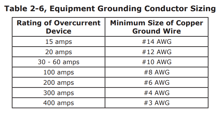
The inverter case and all other noncurrent-carrying exposed metal surfaces in the entire electrical system that may be accidentally energized must be grounded. The equipment-grounding conductor must be sized to safely carry the maximum ground-fault current likely to be imposed on it from where a ground-fault may occur. In accordance with the NEC, use Table 2-6 to size the equipmentgrounding conductors. This table requires that the equipment-grounding conductor be sized according to the rating of the overcurrent device protecting the circuit.
AC Side – Where the AC output from the inverter is connected to an AC load center, there should be an equipment grounding conductor connected between the inverter case and the grounding point in the AC load center. The AC equipment grounding conductor (EGC – AC) is sized per Table 2-6 and is connected to the inverter’s AC equipment grounding terminal shown in Figure 2-8.
DC Side – Since the currents on the DC side are higher than the AC side (10 times at 12 volts, 5 times at 24 volts), the equipment grounding needs are different. The DC equipment grounding conductor (EGC – DC) is sized per Table 2-6 and connected to the DC equipment grounding terminal on the inverter as shown in Item 7, Figure 1-2.
Neutral to Safety Ground Bonding
The standards for safely wiring residential, commercial, RV/truck, and marine installations in the United States require the neutral and safety ground to be connected at the AC source; whether it is the utility feed in your home, an inverter, or a generator. This is to establish a specification that maximizes the possibility that a circuit breaker will activate if a hotwire-to-ground fault occurs. These standards also require that the AC neutral be connected to safety ground (often called a “bond”) in one, and only one, place at any time. The single bond is established in order to make the electrical panel’s neutral line safe, by connecting it to ground. Without this bond, the neutral can have up to 60 VAC with respect to ground. On the other hand, if more than one bond is established, currents can circulate between neutral and ground and cause “ground-loop” currents. These ground-loops can trip GFCIs, cause an electric shock hazard, and may be the reason for other annoying side effects.
In applications where you are using an inverter as one of your AC sources along with another AC source (i.e., utility power or generator), there is the potential of having multiple connections (bonds) between neutral and ground. Therefore, you must ensure that the inverter does not also connect the neutral-to-ground while the other AC source is actively powering the inverter loads. This can be prevented if your inverter is equipped with automatic neutral-to-ground switching.
All MS Series inverter/chargers have automatic neutral-to-ground switching to specifically work in multiple source applications. The MS Series inverters use an internal relay that automatically connects the AC neutral output terminal to the vehicle/boat’s ground while inverting (Inverter mode) to provide the neutral-to-ground bond; as shown in Figure 2-20. However, when an external AC source (i.e., shore power or a generator) is qualified, another neutral-to-ground connection is introduced in the system. When the MS Series is connected to this external AC source and goes into Standby mode, the internal relay automatically opens the neutral-to-ground connection as shown in Figure 2-21. This design keeps two neutral-to-ground connections from occurring at the same time, thereby preventing an electrical shock hazard between the vehicle/boat’s neutral and the external AC source’s neutral.

Disabling the Neutral-to-Ground Connection
All MS Series inverter/chargers have the automatic neutral-to-ground switching feature. In some installations/jurisdictions, this feature must be disabled by disconnecting the neutral-toground connection. If you are not sure whether you must disable this feature, check your local code requirements. The following steps will guide you in disabling the neutral-to-ground switching feature. Note: The neutral-to-ground switching feature cannot be disabled in MS2000 models.
- Locate and remove the AC access cover plate (Item 15, in Figure 1-3) on the side of the MS Series inverter.
- Inside the AC wiring compartment, locate the green wire with the insulated connector; see Figure 2-22. This insulated connector connects the neutral and ground inside the inverter while inverting.
- Pull the two ends of the insulated connector apart to separate the green wire; this will prevent the neutral and ground from connecting inside this inverter.
- Move the two disconnected ends away from each other and push back out of the way. You must ensure that the two connector ends will not have any contact with any other wires within the AC compartment. You may want to use electrical tape to insulate the ends and secure them out of the way.

Connecting a Large Ground Wire
Marine installation requires the ground wire to be the same size or one size smaller than the negative cable. Use the following steps to allow a larger ground wire to be connected.
- Locate the DC ground terminal (Item 7, in Figure 1-2).
- Locate and remove the AC access cover plate (Item 15, in Figure 1-3) on the side of the MS inverter.
- Within the AC wiring area, locate the hex nut on the back side of the DC ground terminal. After locating the hex nut, use a 7/16” wrench/nut driver to remove the hex nut, bolt, lock washer, and DC ground terminal – remove them from the chassis.
- Reverse the removed bolt and place it back in the chassis hole to attach a correctly sized ground cable to the MS Series chassis as shown in Figure 2-23.
- Place the washer and nut on the bolt over the ground cable and securely tightened the nut [from 4 to 5 ft lbf (5.4 to 6.8 N-m)]. Note: The ground cable’s bolt hole size is 1/4”.

Inverter Notification Requirements
When an inverter is installed in a building, facility or structure, the NEC (National Electrical Code) requires a label or plaque to be provided. This label/plaque is required to be easily visible and provide information that informs personnel on the location of all electrical system disconnects. This is to ensure all power to a building is quickly located and shut down in an emergency. There are also specific requirements for this label/plaque depending on the inverter application, they are as follows.
Facilities with Standalone Systems
Any building, facility, or structure with a photovoltaic power system that is not connected to a utility service source and is a standalone system must have a permanent plaque or directory installed on the exterior of the building or structure at a readily visible location acceptable to the Authority Having Jurisdiction (AHJ). The plaque or directory must provide the location of system disconnecting means and information regarding whether the structure contains a standalone electrical power system.
Facilities with Utility Services and PV Systems
Buildings, facilities, or structures with both utility service and a photovoltaic system must have a permanent plaque or directory providing the location of the service disconnecting means and the photovoltaic system disconnecting means if they are not located at the same location.
Inverter Warning Label
A warning label as shown in Figure 2-24 is provided to inform all personnel that an inverter is installed in your electrical system. Affi x this label in a clearly visible location at the electrical panel that is being powered by the inverter. This is because it might be falsely assumed that the panel is no longer “hot” after the AC power has been shut off, when power may actually still be available due to the inverter automatically powering the panel.

Final Inspection
- Verify all cables/conduit runs are secured with wire ties or other non-conductive fasteners to prevent chafing or damage from movement and vibration.
- Verify strain reliefs or grommets are in place to prevent damage to the wiring or conduit where it passes through walls, bulkheads, or other openings.
- Verify all AC connections are correct and torqued to a maximum of 16 in lbf (1.8 N-m).
- Replace the covers on the main electrical/distribution panel.
- Replace the chassis access cover.
- Verify the inverter’s front panel switch is in the “OFF” position.
Functional Test
After all electrical connections to the inverter, batteries, AC source and sub-panel have been completed, follow these steps to test the installation and the inverter’s operation.
- Apply battery power to the inverter by closing the DC circuit breaker. The inverter will remain off, but the green status indicator on the front of the inverter will quickly blink once to indicate that DC power has been connected and the inverter is ready to be turned on.
- Prior to turning on the inverter, make sure all AC loads (i.e., appliances) are NOT connected to the inverter’s output or to any AC outlets powered by the inverter.
- Lightly press and release the inverter’s ON/OFF switch to turn the inverter on. Verify the inverter’s status indicator is blinking – indicating the inverter is on.
- Connect a 10-25 watt light bulb to the inverter output and verify it comes on and shines normally. DO NOT connect anything larger than a 25-watt light bulb until all wiring and voltages are confirmed to be correct.
- Check the AC output voltage of the inverter by connecting an AC voltmeter to the output terminals as shown in Figure 2-25 (verify the correct output voltages).
- Press and release the inverter’s ON/OFF switch to turn the inverter off. The inverter’s status indicator and the connected load should go off.
- Apply AC power to the inverter’s AC input. After the AC input power is qualified (approximately 15 seconds), the incoming AC power will transfer through the inverter to the inverter’s AC output and power the light bulb. Verify that the inverter’s status indicator and the light bulb come on.
- Even though the light bulb is on, the inverter is currently disabled (off). Press and release the ON/OFF switch on the inverter to enable (turn on) the inverter.
- Disconnect the incoming AC power to the inverter. Verify the light bulb remains on and is now powered by the inverter.
If the inverter passes all the steps, the inverter is ready for use. If the inverter fails any of the steps, refer to the Troubleshooting section in this manual.
