Remote Control Panel Operating Instructions
Setup
When the remote is connected to a Magnum inverter/charger, the settings in the remote control determine the inverter/charger operating parameters. The default settings in the remote control (see Table 3-4, Inverter/Charger Default Settings) are adequate for most installations, however you have the option to change some of the operating parameters if required. This section will show you how to navigate the remote, give you an understanding of the function of each adjustable setting and help you decide what setting should be used.
Navigating the Remote’s Menu
The ME-RC has an internal structure that provides menu items and adjustable settings that provide the ability to configure your inverter/charger to your specific parameters.
- LCD Display - The bottom line of the LCD display shows the menu items, adjustable settings or the meters display information.
- Menu Pushbuttons (x5) - These five menus allow simple access to the menu items that can help with configuring, monitoring and troubleshooting your inverter/charger system.
- Rotary SELECT Knob - This knob allows you to quickly scroll through and select various menu items and settings after pressing a menu pushbutton. This knob is also used to “save” a setting once it is displayed on the LCD screen and will refresh the LCD display by holding this knob down for 10 seconds.

 |
 |
 |
 |
Menu Pushbuttons and Menu Items
The five menu pushbuttons (SHORE, AGS, METER, SETUP or TECH) allow the inverter/charger system to be configured to your specific preferences. These menus also allow you to access menu items that can help with monitoring and troubleshooting your system.
Read this section to help understand the function of each Menu pushbutton and the configurable settings - to determine if they should be changed to optimize the operation of the inverter/charger.
SHORE Menu
This menu pushbutton gives a quick means of changing your Shore Max setting to coordinate with the circuit breaker rating from the incoming AC source.
- SHORE: Shore Max - This selection ensures the inverter AC loads receive the maximum current available from the utility or generator power. Whenever the utility or generator is connected to the inverter (thru AC HOT 1), the current used to power the AC loads and to charge the batteries is monitored. When the total current used to power the AC loads and charge the batteries begins to approach the Shore Max setting, the current that was used for charging the batteries will automatically be reduced. This ensures the AC loads have all the available current when needed.
Default setting: Shore Max = 30A

Where to set: Set the Shore Max setting to match the current rating of the utility power or generator’s circuit breaker. If using multiple AC sources (utility and generator) through an AC transfer switch, adjust this setting to the smaller AC breaker size. This setting is very dependent on the stability of the AC source. If using a generator, factors such as altitude and output voltage regulation may require a lower setting than the generator’s breaker size. For best performance, lower this setting to 1/3 its rated capacity and gradually increase while ensuring the voltage level stays above the SETUP: 06 VAC Dropout setting.
| Caution: The Shore Max setting does not limit the current to the inverter loads. If the current from the loads on the output of the inverter are greater than the circuit breaker rating on the incoming AC source, you may experience nuisance tripping on this breaker. |
AGS Menu
The AGS menu pushbutton allows the optional Auto Generator Start (AGS) controller (if installed and networked) to be configured to your specific system preferences and check status of the AGS.
| Note: Refer to the ME-AGS-N Owner’s Manual (part number: 64- 0005) for detailed information on the Magnum Energy Auto Generator Start (ME-AGS-N) and this menu. |

METER Menu
Pressing the METER menu pushbutton gives you access to different meters, which helps determine the status of the inverter/charger and battery system.
- METER: 01 INV/CHG Meter - This menu provides the DC voltage and current while either inverting or charging. The DC: V (Volts) display provides the voltage from the batteries connected to the inverter. The DC: V accuracy is ±1.5% with a 0.1 VDC resolution. While inverting, the DC: A (Amps) displays a negative number to show the battery current used by the inverter. If you are charging, the DC A (amps) displays a positive number to show the amount of current delivered to the batteries. The accuracy of this display below 1 amp AC (~10 amps DC @ 12VDC) is not detected. When the current into or out of the batteries is greater than 1 amp AC, the display accuracy is ±20%.

- METER: 02 BM: SOC thru 06 BM: TECH - These menus allow the optional ME-BMK (Magnum Energy’s Battery Monitor Kit) - if installed - to be configured to your specific system preferences and display the status of the battery system; refer to the ME-BMK Owner’s Manual (part number 64- 0013) for detailed information on the Battery Monitor Kit and these menus.
SETUP Menu
Pressing the SETUP menu pushbutton provides access to the menu items and settings that allow the inverter/charger to be configured. Read each menu item to determine if any setting requires adjustment to meet your requirements.
- SETUP: 01 Search Watts - Allows you to turn off the Search Watts feature or adjust the power level to determine when the search watts feature becomes active. The power level range selection is 5W to 50W. If this feature is not needed, select Search=Off. When search is turned off, the inverter continuously provides full AC voltage to the loads.
Default setting: Search= 5W.
| Note: When the Search Watts feature is active, “Searching” appears on the top line of the LCD display and the green ‘INV’ LED will slowly flash. |

What is the “Search Watts” feature? This feature is used to help save battery power by reducing the inverter’s output to search pulses when there is no detectable load. If someone turns on a load greater than the wattage level setting while the inverter is “searching”, the inverter will start “inverting” to provide full voltage on its output.
Should I use the “Search Watts” feature? If the inverter can spend a great deal of time “searching” (to reduce the power drain on your batteries) and you can tolerate small loads (less than 5 watts) from being on, then the search mode feature should be used. However, if you require some small load (i.e. digital clocks, satellite receivers, answering machines, etc.) to always be on, then this feature should be turned off (Search = Off).
I want to use the Search Watts feature, how do I determine where to set it? The search watts setting should be adjusted to the same power level (or the next lower setting) of the smallest load that you want to run. If you don’t know the wattage of the smallest load you want to run, turn the load on and decrease the Search Watts setting until the load comes on and stays on.
Example: You have reviewed all the loads you want to run and determined that the smallest load is a 30 watt light, then set the Search = 30W. Whenever you turn on any load (because all the loads are greater than 30 watts), the inverter will stop “searching” and start “inverting” to deliver power to the load.
| Note: Even though the search feature is on, some connected equipment may draw enough current even while in the “off” position to keep the inverter in the “inverting mode”. |
- SETUP: 02 LowBattCutOut - The Low Battery Cut-Out (LBCO) setting is used to set the DC voltage level that turns off the inverter to help protect the batteries from over-discharge damage. Selections are from 9.0 VDC to 12.2 VDC (12-volt inverter models), 18.0 VDC to 24.4 VDC (24-volt inverter models), or 36.0 to 48.8 (48-volt inverter models). If the battery voltage drops below the LBCO selected set-point continuously for more than 1 minute, the fault LED will come on, the inverter will turn off, and the display will show a ‘Low Battery’ status. If the battery voltage falls below 8.5 volts (12-volt models), 17.0 volts (24-volt models), or 34.0 (48-volt models); the fault LED and ‘Low Battery’ status will be immediate.
Default settings: LBCO = 10.0 VDC (12-volt models), 20.0 VDC (24-volt models) or 40.0 VDC (48-volt models).
| Note: The inverter will automatically begin to start inverting when the DC voltage increases to ≥ 12.5 VDC (12-volt models), ≥ 25.0 VDC (24-volt models) or ≥ 50.0 VDC (48-volt models). If AC power is available and connected to the inverter’s input, the inverter will automatically clear the ‘Low Battery’ fault, pass the input AC power to the output and begin charging the batteries. |

Where do I set the LBCO setting? If you want to cycle the batteries slightly - but don’t want to discharge them more than 20%*, then the LBCO setting should be set from 11.5 to 12.2 VDC (12-volt models), 23.0 to 24.4 VDC (24-volt models) or 46.0 to 48.8 (48-volt models). In some applications, such as installed in an off-grid home or doing a lot of dry-camping in your RV, you may want to cycle down to 50%* by setting the LBCO from 10.0 to 11.4 VDC (12-volt models), 20.0 to 22.8 VDC (24-volt models) or 40.0 to 45.6 VDC (48-volt models). In extreme circumstances, you have the ability to discharge the batteries to 80%* by setting the LBCO to 9.0 or 9.5 VDC (12-volt models), 18.0 or 19.0 VDC (24-volt models), or 36.0 or 38.0 VDC (48-volt models) before recharging.
| Note: The higher the LBCO setting, the less the inverter will discharge the batteries; which should allow the batteries to have a longer life. The downside to a higher LBCO setting is that you need to charge more often to prevent the inverter from shutting down. |
| Note: If there is an Auto Generator Start device installed, it should be set to start ≥1.0 volts higher than the LBCO setting – this is to prevent the inverter from shutting down before the generator comes on. |
- SETUP: 03 Batt AmpHrs - Used to select the approximate capacity of the battery bank connected to the inverter. This setting determines the time the battery charger is in the Absorb Charging stage (i.e. Absorption Time). See Table 3-1 to correlate the battery capacity to the Absorption Time; selections are in 10 AmpHrs increments from 200 to 2500 AmpHrs.
Default setting: Batt AmpHrs= 400

Where do I set the Battery Amp-Hour setting? Select the setting based on the 20-hour Amp-Hour (AH) capacity of your battery bank.
How do I determine my Battery Amp-Hour capacity? The inverter requires deep cycle batteries, which are specifically made for continuous use. Deep cycle batteries are rated either by a) amp-hours or b) reserve capacity in minutes.
- Amp-hour (AH) capacity is a measurement of how many amps a battery can deliver for a specified length of time (usually 20 hours) until the voltage achieves 1.75 VDC / cell at 80° F.
- Reserve Capacity (RC) is a measure of how many minutes a battery can deliver a certain amount of current (usually 25A) and maintain a voltage above 1.75 VDC/cell at 80° F.
| Note: If using the Reserve Capacity (25A), the 20-hour AH capacity can be estimated by multiplying “minutes reserve capacity” by 50%. |
Table 3-2 below provides an estimated 20-hour Amp-Hour capacity based on the group/code size, physical size and voltage of the battery. If you are not sure of your battery’s 20-hour AH rating, consult your battery manufacturer/ dealer or use the table below to obtain an estimate.

Once you’ve determined the Amp-hour capacity of each battery, review how your batteries are connected (parallel or series) to determine the total amphour capacity of the battery bank:
- Parallel connection – batteries connected in parallel (positive to positive, negative to negative) increase the amp-hour capacity of the battery bank, but the voltage remains the same. For example: You have a 12-volt battery bank with three 12-volt batteries that are rated at 125 Amp-Hours (AH) each. Each of the positive terminals are connected together and each of the negative terminals are connected together, which means they are connected in parallel. The amp-hours of each battery connected in parallel are added together (125 AH + 125 AH + 125 AH = 375 AH), but the voltage of the battery bank stays the same (12 VDC).
- Series connection - batteries connected in series (positive to negative) increase the voltage of the battery bank, but the amp-hour rate remains the same. For example: You have a 12-volt battery bank with two 6-volt batteries that are rated at 220 amp-hours. The positive terminal of the first battery is connected to the negative terminal of the second battery, which means these batteries are connected in series. Since the two 6-volt batteries are connected in series, the voltage of the batteries are added together to produce 12-volts (6 VDC + 6 VDC = 12 VDC), but the amp-hour capacity of the battery bank does not change (220 AH).
In battery banks where you have batteries connected in series and in parallel –the rules are the same. The batteries connected in series are referred to as a “series string” and the amp-hour capacity doesn’t change. Each “series string” is connected together in parallel to increase the amp-hour capacity. Add the amp-hour capacity of each “series string” connected in parallel to determine the total amp-hour capacity of the battery bank.
- SETUP: 04 Battery Type - Used to select the battery type, which determines the battery charge profile and ensures the batteries are receiving the proper charge voltage. The fixed voltage selections are GEL (for Gel batteries), Flooded (for liquid lead acid batteries), AGM 1 (for Lifeline AGM batteries) and AGM 2 (for East Penn/Deka/Discover/Trojan AGM batteries); The ‘Custom’ selection allows the Float and Absorb charge voltage settings to be individually adjusted. See Table 3-3 to determine the specific charge voltage based on the Battery Type selected.
Default setting: BattType = Flooded
| Note: The voltage settings shown in Table 3-3 are based on the Battery Temperature Sensor (BTS) being disconnected or at a temperature of 77° F (25° C). If the BTS is connected, the actual charge voltage will increase if the temperature around the BTS is below 77° F (25° C) and decrease if higher than 77° F (25° C). This ensures the batteries receive the correct charge voltage even if they become cold or hot. |


- SETUP: 05 Charge Rate - Used to set the maximum charge rate allowed to charge the batteries during bulk, absorption, float and equalize charging. Selections are ‘Max Charge = 0%’ up to ‘Max Charge = 100%. The Max Charge = 0% setting is available to help minimize charging while continuing to allow pass-thru power. The rest of the selections are provided to limit the charge rate to the battery bank, which helps prevent battery overheating caused by charging at too high a charge rate.
The Max Charge selections are provided as a percentage of the inverter/ charger’s maximum charging capability. Refer to label on the side of the inverter or the operator’s manual for the inverter/charger to determine its maximum charge rate. Once you find this maximum charge rate, determine the percentage needed to limit the charge rate to your battery-bank.
For example, if the maximum charge rate of your inverter/charger is 100 amps and you need to limit the charge rate to 50 amps, choose the Max Charge = 50% selection (50 amps = 50% of 100 amps).
Default setting: Max Charge = 80%

| Note: If the Max Charge rate is set to 0%, the topology of the Magnum Inverter - when connected to an AC source - will over-ride the 0% setting and start charging if the battery voltage is <7 VDC (12 VDC models), <14 VDC (24-volt models) or <28 VDC (48-volt models). |
How do I determine where to set my maximum charge rate? The maximum charge rate is generally set to a C/5* rate (C = the total amphour capacity of the battery bank - using the 20-hour AH rate). The C/5 rate is usually used when the objective is to charge the batteries as quickly as possible (i.e. 400 AH ÷ 5 = 80 amp maximum charge rate). A lower rate such as C/20* is used when the batteries need to be charged as slow as possible.
| Caution: The C/5 or C/20 charge rate settings are guidelines; they are not requirements on how you should set your battery charge rate. For specific charge rate requirements, refer to your battery manufacturer. |
| Note: If multiple inverter/charger’s are used on a single battery bank, you must ensure that the total charge rate from all inverter/chargers is limited to the maximum charge rate needed for your battery bank. The Max Charge rate only limits the charging on each inverter/charger individually, not on all inverter/chargers. |
- SETUP: 06 VAC Dropout - Used to select the minimum AC voltage that must be present on the input before the inverter/charger switches from inverter to charger mode. For example: If this setting is set to Dropout = 60 VAC, then the AC input voltage must be above 60 Volts before the inverter will switch from inverter mode to charge mode.
This setting also determines the minimum AC voltage threshold where the charger disengages and the inverter (when turned on) will provide AC power from the batteries. This protects AC loads from utility outages. For example: If this setting is set to Dropout = 60 VAC, when the AC input voltage drops to 60 volts, the inverter will switch from charge mode to inverter mode.
Settings are Dropout = 60 VAC to 100 VAC for 120 VAC inverters (or Dropout = 120 VAC to 200 VAC for Export models) and Dropout = UPSmode.
Default setting: Dropout = 80 VAC (Export inverter models = 160 VAC)

Where do I set my VAC Dropout? It depends on the application and what you are using as the AC source. The settings not only look at the incoming voltage level to determine when to transfer, but also determines how quickly the charger disconnects and starts inverting based of the fluctuations of the incoming AC voltage.
- Dropout = 60 VAC to 100 VAC (For Export Inverter Models: Dropout = 120 VAC to 200 VAC): Use a VAC Dropout setting from 60 VAC to 100 VAC (Export models: Dropout from 120 VAC to 200 VAC) when the AC source may have fluctuations in RMS voltage. These settings attempt to prevent the charger from disengaging unnecessarily due to poor quality voltage; and are highly recommended if using a generator for charging. The transfer time from charge mode to inverter mode is >16 milliseconds when using these settings.
- Dropout =UPSmode: Use the ‘UPSmode’ setting when the AC source is well regulated above 105 VAC (210 VAC for Export inverter models) and the inverter loads are sensitive to voltage fluctuations. This setting is intolerant of voltage fluctuations and will provide a quick transfer. The transfer time from charge mode to inverter mode is ≤16 milliseconds when using this setting. For generator charging, do not use this setting.
| Note: If you get nuisance AC disconnects. Either change the setting to 100 VAC or less (Export inverter models: 200 VAC or less) or obtain a better voltage regulated AC source. |
- SETUP: 07 Power Saver - This setting allows you to turn off the Power Saver™ feature or select the time (from 1 minute to 60 minutes) that determines how often the display goes into Power Saver mode.
Default setting: PwrSave = 15min

What is the power saver feature? The Power Saver feature causes the LCD backlight and LED’s on the remote display to turn off to conserve energy. The remote goes into Power Saver mode if there hasn’t been a pushbutton press or fault message for a period of time (this time is determined by the SETUP: 07 Power Save setting). Whenever the remote goes into the Power Saver mode, the LCD backlight and LED’s can be reactivated by pressing any menu pushbutton. If you have a fault during the Power Saver mode, the LCD backlight and Fault LED will come on and stay on as long as the fault is detected.
If you want the LCD backlight and LED’s to always be on, you will need to turn the Power Saver feature off by selecting PwrSave = Off.
- SETUP: 08 Screen Setup - Used to adjust the contrast of the LCD screen and backlight brightness for the best looking display based on the current lighting conditions and viewing angle.
Default settings: Contrast = 100%; Brightness = 50%

Operation
This section explains how to operate the inverter/charger. It also helps to explain the operational status determined by the LED indicators and LCD display.
Front Panel
The ME-RC front panel contains LEDs and a LCD display for viewing system status; pushbuttons to control system operation; and a Rotary Knob that allows an easy way to select and find system information.

LED Indicators
There are four LED’s indicators on the front panel that light solid or blink to indicate the inverter/charger’s status. When the remote is first powered-up, all the LED’s come on as it goes through a self-test. Once the self-test is complete, the LED’s along with the LCD provide the operating status of the inverter/charger. See section 5.3.4 for the LED Indicator Guide.
LCD Display
The LCD display is used for setting up the system operation as well as viewing the current operating status or any fault condition. This display has two lines of alphanumeric characters and features a back-light that can be set to turn off to conserve power. The top line provides the inverter/ charger status, which is detailed in this section. The bottom line displays battery information while using the METER menu, system troubleshooting information while in the TECH menu and menu items that can be configured for your specific system operation while in the SETUP menu. This display automatically powers up with the current system status on the top line and the Home Screen (detailing the inverter’s DC voltage and current as shown in figure 5-1) on the bottom line.
ON/OFF Pushbuttons
- ON/OFF INVERTER: This pushbutton toggles the inverter function on and off. The green “INV” LED turns on and off with the pushbutton.
- ON/OFF CHARGER: This pushbutton toggles the charger function on and off whenever the charger is actively charging. The green “CHG” LED turns on and off with this pushbutton. This pushbutton is also used to initiate an equalize charge; for more information on using the equalize charge feature, see section 5.2.2 and the Equalizing Mode information.
Menu Pushbuttons
These five menu pushbuttons provide quick access to menu items that can help with configuring, monitoring and troubleshooting your inverter /charger system.
- SHORE: This pushbutton allows you to set the appropriate breaker size for the incoming utility/shore power and is used to control the amount of AC amps the battery charger uses from the HOT 1 IN input; see section 3.2.1 for more detailed information.
- AGS: This pushbutton allows the networked Auto Generator Start (MEAGS-N) controller to be configured to specific system preferences and check status of the AGS (when connected). Refer to the ME-AGS-N Owner’s Manual (part number: 64-0005) for detailed information on this menu.
- METER: This pushbutton provides meter information on the inverter/ charger system; see section 3.2.3 for more detailed information.
- SETUP: This pushbutton allows the inverter/charger to be configured to your specific system preferences; see section 3.2.4 for more detailed information.
- TECH: This pushbutton allows you to access menu selections that can help service personnel with troubleshooting and also allows the factory default setting to be restored; see section 3.2.5 for more detailed information.
Rotary SELECT Knob
The Rotary ‘SELECT’ knob is similar to a dash radio knob and used to easily view and select various menu items and settings displayed in the LCD screen. Turn the rotary knob clockwise and counterclockwise to view the different menu items and available charger and inverter settings. Push or “SELECT” the rotary knob to enter a menu item or to “save” a setting once they are displayed on the LCD screen.
| Note: All adjustable inverter/charger settings in the ME-RC (except for the SHORE: Shore Max and SETUP: 08 Screen Setup settings - which revert back to default) are saved in non-volatile memory and are preserved until changed - even if an inverter reset is performed or if all power to the remote or inverter is removed. |
| Note: The LCD display can be refreshed by holding down the SELECT knob for 10 seconds. |
| Caution: An accessory that is networked to the inverter may have adjustable settings that revert back to default if all power to the inverter is lost. Refer to the operation manual for the particular accessory to determine if any setting for the accessory is affected. |
Operating the Inverter/Charger
Inverter Mode:
- Turning the inverter on: Press the ON/OFF INVERTER pushbutton to activate the inverter function. The inverter will either be actively “inverting” by using power from the batteries to power the AC loads (see figure 5-4); or will be “searching” for a load by using very little power from the batteries - if in search mode (see figure 5-3). The green ‘INV’ LED will be on when the inverter is actively inverting and the green ‘INV’ LED will flash while searching.
- Turning the inverter off: While the inverter is actively “inverting” or “searching”, the ON/OFF INVERTER pushbutton can be pressed to switch the inverter function off and this will turn the green ‘INV’ LED off (see figure 5-2).
- Inverter Standby: The inverter is in standby when the inverter is active (green ‘INV’ LED is on) and an external AC power (utility/shore or generator) is passing through the inverter to power the AC loads. During normal operation, the AC loads will be powered by the external AC power, however, if a blackout or brownout condition occurs, the inverter senses these conditions, transfers to inverter mode and powers the AC loads connected to the inverter.
| Caution: : If you have critical loads and in Inverter Standby, do not press the ON/OFF INVERTER pushbutton to turn the inverter function off. If the green ‘INV’ LED is off, inverter power will NOT be available to run your critical loads if the external AC power is interrupted. |
Charger mode
- Turning the charger on: The charger will automatically be activated and begin to charge your batteries when acceptable AC power (utility/shore or generator) is connected to the input (HOT IN 1) of the inverter. When the charger is ON, it produces DC voltage and current to charge your batteries. The CHG LED will be on when the charger is ON and actively charging. While charging the display will show Bulk, Absorption, Float or Full Charge (see figures 5-5 thru 5-9).
- Charger Standby: While the charger is actively charging, the ON/OFF CHARGER pushbutton can be pressed to switch the charger to “Charger Standby”. While the charger is in Charger Standby, the incoming AC is still available on the inverter’s output, but the charger is not allowed to charge. The display will show ‘Charger Standby’ and the CHG LED will flash when the charger is in standby mode, (see figure 5-10).
| Note: To resume charging, momentarily press the ON/OFF CHARGER button; or disconnect/reconnect AC power to the inverter’s input. |
- Equalize charging: Equalizing is a “controlled overcharge” performed after the batteries have been fully charged. It helps to mix the battery electrolyte (to reverse the buildup of stratification) and also helps to remove sulfates that may have built up on the plates. These conditions, if left unchecked will reduce the overall capacity of the battery.
| Warning: Do not perform an equalization charge without reading and following all safety precautions pertaining to charging/equalization as noted in this manual and any equalization information in the inverter’s manual. |
System Status Messages
The remote control uses the top line of the LCD display to show the inverter/ chargers current operation by displaying a status message. This section will show the inverter/ charger’s operating modes and the available status messages under each mode. Use these status messages along with the Status LED’s to determine the inverter/charger’s current operating status and to help troubleshoot the system if a fault occurs.
There are three operating modes of the inverter/charger:
- Inverter Mode
- Charger Mode
- Fault Mode
Inverter Mode Messages
The inverter/charger will be in the Inverter Mode when AC power (shorepower/utility or generator) is not available or unacceptable to the inverter/charger’s input. The Inverter Mode messages are Off, Searching and Inverting.

- Off – This message tells you that there is no AC available on the inverter’s AC output. The inverter function is off and there is no utility/shore or generator power AC sensed on its input.

- Searching – The inverter is in the Search mode, which means the AC loads on the inverter output are less than the SETUP: 01 Search Watts setting. The search mode function is used to reduce the inverter draw from the battery and may be turned off at any time if you want full inverter output voltage available at all times (see the SETUP: 01 section).

- Inverting - The inverter is providing AC voltage on its output by inverting power from the batteries.
Charger Mode Messages
When AC power (utility or generator) is connected to the inverter/charger, it begins to monitor the AC input for acceptable voltage. Once the AC input is accepted, the AC transfer relay (inside the inverter) closes and charger mode begins. There are several charger mode messages; view the top line of the LCD display and the corresponding message in this section to determine and understand the particular charger mode.
| Note: The AC input becomes acceptable after a minimum 10 second delay and when the voltage is greater than the SETUP: 06 VAC Dropout setting. |

- Charging – Once the charger mode has been enabled, the unit will wait and display “Charging” to determine the charge routine. If the DC voltage is low (≤12.8 VDC/ 12-volt models, ≤25.6 VDC / 24-volt models, or ≤51.2 VDC / 48-volt models), the charger will initiate “Bulk Charging”. If the DC voltage is high (>12.9 VDC / 12-volt models, >25.6 / 24-volt models or >51.2 / 48-volt models), the charger will skip the Bulk and Absorb charging stages and go directly to Float Charging.

- Bulk Charging – The battery charger is delivering maximum current (determined by the SETUP: 05 Charge Rate setting) to the batteries. The charger will remain in bulk charge until the absorb voltage (determined by the SETUP: 04 Battery Type setting) is achieved.

- Absorb Charging - The absorb charge state is the constant voltage stage and begins when the absorb voltage is reached (determined by the SETUP: 04 Battery Type setting) while bulk charging. During this stage, the DC charging current decreases in order to maintain the absorb voltage setting. This charge stage continues until the Absorb Charging time (determined by the SETUP: 03 Battery AmpHrs setting) is finished.

- Float Charging – At the end of the Absorb Charging time, the charger reduces the charge voltage and tries to maintain the batteries at the float charge voltage setting; which is determined by the SETUP: 04 Battery Type setting as shown in Table 3-3, Battery Type to Battery Charge Voltages.
| Note: : If the battery voltage falls ≤12.1 VDC (12-volt models), ≤24.2 VDC (24-volt models) or ≤48.4 VDC (48-volt models); the unit will begin bulk charging. |

- Full Charge – This status indicates that you have entered the Battery Saver™ mode. This mode maintains the batteries without overcharging, thus preventing excessive loss of water in flooded batteries or drying out of GEL/ AGM batteries. After 4 hours “Float Charging”, the charger will turn off and “Full Charge” is displayed (charger is now in Battery Saver™ mode). If the battery voltage drops to ≤12.6 (12-volt models), ≤25.2 (24-volt models) or ≤50.4 (48-volt models); the charger will automatically initiate another 4 hours “Float Charging”. This cycle helps to ensure the batteries are monitored and maintained; and continues as long as AC power is continuously connected to the AC input.
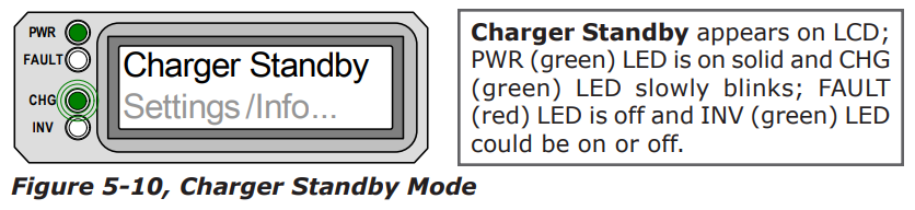
- Charger Standby - This means the charger has been disabled to prevent any charging, but the AC power (from shore/utility or generator) to the AC input is still available on the AC output. This display is shown when the ON/OFF CHARGER pushbutton is pressed while the AC power is passing thru the inverter/charger.
| Note: To enable charging again, press the ON/OFF CHARGER pushbutton. When the charger is again enabled, the charger will continue in the charge mode it left and the CHG (green) LED will come on solid. |

Equalizing:
- The battery charger is delivering the equalize voltage to the batteries; see Table 3-3, Battery Type to Battery Charge Voltages to determine the equalize voltage for your battery type.
- Equalize charging can be enabled by the ON/OFF CHARGER pushbutton - if the SETUP: 04 Battery Type selection allows. Equalization charging can only be enabled while the charger is in float charge or in Battery Saver mode. To turn on equalize charging, ensure the LCD display reads “Float Charging” or “Full Charge”, then press and hold the ON/OFF CHARGER pushbutton down (about 5 seconds) until the LCD screen displays “Equalizing”.
- The equalize charge will continue for 4 hours and then automatically stop and return to “Float Charging”. The equalize charge can be manually stopped by pressing and holding the ON/OFF CHARGER pushbutton down (about 5 seconds) until the LCD screen displays “Float Charging”.
- During equalize charge stage the batteries will begin gassing and bubbling vigorously which consumes water; ensure each cell has adequate distilled water levels prior to equalizing and add water as needed after equalizing.
How often should I equalize?
- Some experts recommend that heavily used batteries should be equalized periodically, ranging anywhere from once a month to once or twice per year. Other experts only recommend equalizing when the cells have a low specific gravity or when the difference between any individual cell has a specific gravity reading greater than .015 after being fully charged.
How long should I equalize?
While the batteries are gassing, monitor the specific gravity readings every hour; when the specific gravity readings no longer increase, the equalization charge is complete and should be stopped.
| Warning: Equalizing produces hydrogen and oxygen gas. Ensure the battery compartment has adequate ventilation in order to dissipate this gas to avoid explosions. |
| Caution: Ensure you batteries can be equalized - only equalize your batteries if permitted by your battery manufacturer or dealer. Performing an equalize charge on batteries other than liquid lead acid or certain AGM types could permanently damage them. Refer to your battery manufacturer/dealer for instructions on how to properly equalize your batteries. |
| Caution: Ensure the DC loads will not be damaged by the higher voltage applied to the batteries during the equalize charge. If in doubt, disconnect the DC loads to prevent damage. |
| Note: Equalization charging is not available if GEL or AGM 2 is selected under the SETUP: 04 Battery Type menu. |
Fault Mode Messages
The fault LED comes on and a fault status is displayed when an abnormal condition is detected. View the LCD display and the information in this section to determine and correct the issue.
| Note: Many of the faults will automatically restart when the fault is cleared. Some faults will require a manual restart; this requires the ON/ OFF INVERTER pushbutton on the remote to be pressed and released. Finally, if the fault is unable to clear, an inverter reset may be required - see section 6.2 to perform an inverter reset. |
System Fault messages: These fault messages are usually caused by some external issue that directly affects the inverter/charger system.

- Low Battery – The inverter turned off to help prevent the batteries from being over-discharged. This message is displayed and the FAULT (red) LED illuminates when the battery voltage drops below the SETUP: 02 LowBattCutOut (LBCO) setting for more than 1 minute. The inverter will automatically restart and resume operation when the battery voltage rises to ≥12.5 VDC (12-volt models), ≥25.0 VDC (24-volt models), or ≥50.0 VDC (48-volt models).
| Remedy: This fault will also automatically restart if AC power (such as utility/shore power or a generator) is connected to the inverter/ charger’s input and battery charging begins. |

- High Battery – The inverter has turned off because the battery voltage is at a very high level. This fault message is displayed and the FAULT (red) LED will be on when the battery voltage is above the High Battery Cut-Out (HBCO) value. This fault will automatically restart and resume operation when the battery voltage drops 0.3 VDC (12-volt models), 0.6 VDC (24-volt models), or 1.2 VDC (48-volt models) below the HBCO value.
| Note: The HBCO value is dependent on your inverter revision and model. Normally, the HBCO value for the ME/MM/RD Series inverters is 16 VDC (12-volt models) or 32 VDC (24-volt models); and the HBCO value for the MS/MMS Series inverters is 17 VDC (12-volt models), 34 VDC (24-volt models), or 68 VDC (48-volt models). |
| Remedy: This fault usually only occurs when an external DC charging source is charging the inverter’s battery bank. Turn off any other additional charging source to allow the DC voltage level to drop. |

- Overtemp – This fault message indicates the inverter/charger has shut down because the internal power components (FET’s and/or Transformer) have exceeded their safe temperature operating range. When the unit has cooled down, it will automatically restart and continue operation.
| Remedy: If the fault occurs while inverting, reduce the load on the inverter; if it occurs while charging, turn down the charge rate. If this fault happens often, ensure the inverter is not in a hot area, has proper ventilation and the cooling fans inside the inverter are working. |

- AC Overload - This fault message displays when the AC load on the inverter/ charger’s output has exceeded the inverters AC current protection limits. If the overload condition lasts for less than 10 seconds, the unit will automatically restart and resume operation. However, if the overload occurs more than 10 seconds, the unit will shut down and will require a manual restart.
| Remedy: This fault usually occurs because the connected AC loads are larger than inverter’s output capacity, there is a wiring short on the output or the output wires are incorrectly wired. Once the AC loads are reduced or the output wiring is corrected; the inverter can be restarted after a manual restart has been accomplished. |

- AC High Volts AC - This fault causes the charger to be disabled because a very high AC voltage (>150 VAC) has been detected on the AC input.
| Remedy: Remove all AC power from the inverter’s AC input for at least 15 minutes to automatically restart this fault; ensure only 120VAC power is connected to each of the inverter’s AC inputs. |

- Dead Battery Charge – This fault has detected a very discharged battery bank or a battery bank that is disconnected from the inverter. The unit is attempting to enter the charge mode, but has detected less than 9 volts (12-volt models), 18 volts (for 24-volt models) or 36 volts (for 48-volt models) on the battery bank. This fault will continue until current is able to flow into the battery from the battery charger. Once this happens, the fault will automatically restart.
|
Remedy: Check the DC voltage on the inverter’s DC terminals and ensure it is the same as the battery bank, these two voltages should be very close (<0.5 VDC difference). If not, check to ensure all connections are tight and the fuse/circuit breaker between the inverter and battery bank is good. This fault clears when the AC input is removed or when greater than 9 volts (12-volt models), 18 volts (for 24-volt models) or 36 volts (for 48-volt models) is detected by the inverter when charging. |

- Overcurrent - This fault causes the inverter to shutdown to protect internal power components and may be caused by an excessive AC load. If the overload condition lasts for less than 10 seconds, the unit will automatically restart and resume operation. However, if the overcurrent condition occurs more than 10 seconds, the unit will shut down and will require a manual restart.
| Remedy: This fault usually occurs because the connected AC loads are larger than the inverter’s output capacity, there is a wiring short on the AC output or the wires are incorrectly wired. Once the AC loads are reduced or the output wiring is corrected; manually restart the inverter to resume operation. If this fault condition continues after all these recommendation, perform a inverter reset (see section 6.2). |

- FET Overload - This fault message indicates the inverter/charger has shut down because the internal FET’s (Field Effect Transistor’s) have quickly exceeded a safe operating temperature. When the FET’s have cooled, the unit will require a manual restart to resume operation.
| Remedy: If the fault continues to occur, disconnect all the inverter’s AC output wires and reset the inverter (see section 6.2). If this fault does not clear after doing a reset, the inverter may require service. |

- Breaker Tripped - The inverter has detected that the AC input breaker on the inverter/charger has opened due to excess current flow thru the inverter to the AC loads.
| Remedy: After reducing the AC loads, push in the inverter’s AC input circuit breaker to reset and resume operation. |
| Note: While in charger mode, the inverter’s AC input breaker could nuisance trip if the loads on the inverter’s AC HOT OUT 1 exceed the current rating of this circuit breaker. |
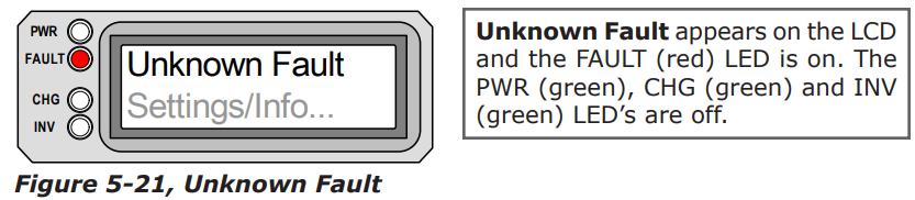
- Unknown Fault - This fault message displays when the inverter/charger has sent a fault code that cannot be determined by the remote.
| Remedy: Call the Technical Support department at Magnum Energy for assistance to help determine and understand the actual fault status. |

- Tfmr Overtemp - This fault message is displayed when the TCO (Temperature Cut-Out) opens and causes the inverter to shutdown to protect the internal power transformer from damage. When the TCO has cooled down, the inverter will automatically restart and resume operation.
| Remedy: If the fault occurs while inverting, reduce the load on the inverter; if it occurs while charging, turn down the charge rate. If this fault occurs often, ensure the inverter is in a cool location, has adequate ventilation and the internal cooling fans are operational. |
Remote Fault Message
The remote control may not be functioning correctly and can also display a fault condition. Refer to the following fault message to help troubleshoot the remote.

- Fatal Error $ - This fault message indicates that the remote’s internal data addressing was unrecognizable; similar to a computer lock-up.
| Remedy: Reset the remote by disconnecting the remote communications cable from the inverter for 5 seconds and then reconnect (see figure 2-2). If the fault continues after resetting the remote, the remote requires service at an authorized service facility. |
| Note: The bottom line may not display correct information while the Fatal Error $ fault condition is displayed; ignore any remote display information during a Fatal Error $ fault. |

- No Inverter Comm - This fault message indicates that the remote is no longer receiving any communication data via the Magnum Network.
| Remedy: Reset the remote by disconnecting the remote communications cable from the inverter for 5 seconds and then reconnect (see figure 2-2). If the fault continues, check/replace the remote cable. |
Stacking Fault Messages
A fault condition may occur when two inverters are stacked in series - using the stacking interface to provide 120/240VAC output - that is not possible on a single inverter installation. Refer to the following fault messages to help troubleshoot the inverters.

- StackClock Fault - There is a stacker cable problem; or 2. One inverter is losing synchronization with the other inverter.
|
Remedy:
|
| Note: This fault has been known to occur when a Magnum Energy accessory is plugged into the Stack Port, but the installation is not using multiple inverters in a stacked configuration. If this occurs, perform an inverter reset (see section 6.2). |

- Stack Mode Fault - This unit has detected a problem with the “other” stacked inverter, check that unit for a fault condition.
| Remedy: This fault will automatically clear when the fault with the other inverter is corrected. |

- StackPhase Fault - 1. The AC input wiring is incorrect; or 2. One phase was lost from the AC input source; or 3. One of the inverter’s internal transfer relay is bad; or 4. The inverter’s AC input circuit breaker may be open.
| Remedy: If this fault doesn’t clear after checking these four recommendations; perform an inverter reset (see section 6.2). |
Internal Fault Messages
The inverter continually monitors several internal components. If an condition inside the inverter occurs that does not allow proper operation, the inverter will shutdown to help protect itself. To clear these “internal” type of faults, the inverter will require an inverter reset.
| Remedy: Perform an inverter reset; see section 6-2. After resetting the inverter, press the ON/OFF INVERTER pushbutton to turn the inverter on and verify the fault has cleared. If the “internal” fault remains, the inverter will require repair at an Authorized service facility. |

- Internal Bridge – This fault message displays and the inverter shuts down because the internal power-bridge protection circuit has been activated.

- Internal Charger - This fault message displays and the inverter shuts down because the internal charger protection circuit has been activated.

- Internal NTC - This fault message displays and the inverter shuts down because the internal NTC (temperature sensor) circuit has been activated.

- Internal Relay - This fault message displays and the inverter shuts down because the internal AC transfer relay protection circuit has been activated.
LED Indicator Guide
The remote provides the following LED’s; use them along with the LCD display to determine the operating status.

Troubleshooting
The remote may not be functioning correctly, use the following table to help find a solution.

Performing an Inverter Reset
Press and hold the Power ON/OFF pushbutton (see figure 6-1) for approximately fifteen (15) seconds until the Charging/Inverting Status LED comes on and flashes rapidly; once the rapid flashing has begun, release the Power ON/OFF pushbutton. The Status LED will go off after the pushbutton is released.
After the inverter reset is completed, press the ON/OFF pushbutton to turn the inverter ON.
Some older inverter models do not allow an inverter reset, if the inverter reset fails, you will need to power-down the inverter using the procedure below. In either case, if an “internal fault” does not clear, the inverter will require repair at an authorized service facility.
| Info: The Power ON/OFF pushbutton is a small momentary type switch which operates by lightly pressing and releasing. |
| Info: All adjustable inverter/charger settings in the ME-RC (except for the SHORE: Shore Max and SETUP: 08 Screen Setup settings - which revert back to default) are saved in non-volatile memory and are preserved until changed - even if an inverter reset is performed or if all power to the remote or inverter is removed. |

Powering-down the Inverter
Perform the following steps to power-down the inverter:
- Remove all AC power (utility or generator power) to the inverter.
- Disconnect the positive battery cable to the inverter.
- Ensure the inverter and remote control are disconnected from all AC and DC power (the remote display will be blank).
After the inverter has been disconnected from all power for 30 seconds, reconnect the positive battery cable and resume operation.
| Info: There may be a momentary spark when the positive battery cable is connected to the inverter’s terminal; this is normal and indicates that the inverter’s internal capacitors are being charged. |