05 Major Appliances
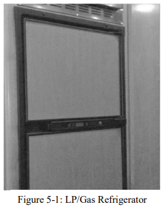
LP/GAS Refrigerator
Your coach may be equipped with a standard LP/gas refrigerator. When this refrigerator is in the “LP gas” mode, make sure that the main LP gas valve is in the “on” position before attempting to start the refrigerator. Please note that the refrigerator is equipped with a semi-automatic energy selector (AES) control system which can be set automatically to switch between a 120volt AC system or a LP-gas operation system when available.
A 12-volt power supply (e.g., 12 VDC system of the motorhome, auxiliary battery, converter, or motorhome engine battery) is required for proper operation of the electronic control panel. For 120 VAC electrical operation of the refrigerator, either the 30 AMP shore power line must be connected or the on board generator must be running, or the refrigerator is also connected into the inverter system to provide the necessary 120-volt AC power.
Note: Running the refrigerator on inverter power for prolong periods of time will drain the motorhome batteries.
To operate the refrigerator in the LP-gas mode, the main LP gas valve must be “open.” For specific instructions on refrigerator please refer to the operating booklet found in the Owner’s Information Package.

Microwave Oven
The Wayfarer contains a convection microwave. All microwave ranges operate on 120-volt AC electrical power, supplied either by the external electrical hookup or by the onboard electrical generator in the motorhome. Touch pad controls are used for operating the convection microwave (i.e. cooking temperature, mode, power level, and cooking time). For basic operating instructions, care, and maintenance for the proper use of the microwave, please consult the specific manual in the Owner’s Information Package.

Cooktop
The Wayfarer is equipped with a standard recessed two burner range (Figure 5-4).
Do not attempt to adjust the cook tops pilot light as it has been factory adjusted and factory set. To extinguish the cook top pilot light when use of the cook top is concluded, push inward on the cook top control knob and turn the knob clockwise to the "OFF" position (Figure 44.2).
To operate either of the two burner recessed cook top burners, light the burners by turning "ON" the gas control knob, wait a couple of seconds and the push the DSI (Direct Spark Ignition) button until a flame appears ( Blue Arrow Figure 44.3).
If the burner does not start after a few attempts, discontinue the process and let the released gas dissipate and then try the process again. The burner knobs operate in a counter clockwise manner and must be gently pushed inwards as they are being turned. Never use the cook top when the motorhome is in motion.
It is wise to have a qualified service technician periodically check the entire propane (LP) gas distribution system in your Wayfarer motorhome. Scheduling such an inspection annually would be a recommended, preventive maintenance routine for every motorhome owner.


Water Heater

Before the water heater is to be used, fill the fresh water system and purge the water lines to and from the water heater by opening all of the hot water faucets in the motorhome. Do so until water steadily flows from each faucet with no "spurting" or "hissing" sounds are heard.
The water heater uses either propane (LP) gas or 110V AC electric to operate the heater. Proper and safe operation of the water heater requires that all safety information provided in the manufacturers owner's manual be read and understood before placing the water heater into service. Take the necessary time to become familiar with this manual which is provided in the Owner's Information Package.
The water heater is designed for operation either with LP gas or 120-volt AC electricity.
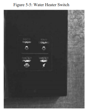
NOTE: When you turn “on” the switch for the water heater the middle red button will light up. It will go off after several seconds—this means the water heater is lit. However, if the light stays illuminated, then that means the water heater has not ignited.
LP Gas – Electronic Ignition Operation
1. If the water heater fails to operate because of high water temperature, the heater will go into a lockout condition (indicator light “on”). When the water eventually cools, reset the system by turning the switch to the “off” position for at least 30 seconds, then turn the switch back “on.”
2. If a lockout condition persists, contact your authorized dealer.
120- VOLT AC ELECTRICAL OPERATION
1. For electrical operation, use the Water Heater switch found on the master control panel in the galley of the coach.
2. Completely fill the water heater with water and purge the hot-water lines of any trapped air.
3. Turn the Water Heater switch “on.” NOTE: Turning the power “on” to the water heater without having previously covered the water-heating element with water may burn out the element and void the warranty.
4. After a while, check the water heater for proper operation; the water temperature should be approximately 140°F (60°C).
5. If the manual-reset, high temperature-limit switch should trip the circuit breaker; reset the switch by depressing the reset button – use a pencil or other non-metallic object to depress the reset button. If the high-temperature limit switch should again trip the circuit breaker, contact an authorized service technician or an authorized dealer.
6. Both the electrical and gas operations of the water heater may be used simultaneously to reduce recovery time of heating water up to desired temperature.
For general maintenance of the water heater or specific information about select steps in operating the water heater, please refer to the owner’s manual for this appliance contained in the Owner’s Information Package.

WATER HEATER STORAGE
Figure 5-6: Water Heater if the motorhome is to be stored during the winter months, the water heater should be drained to prevent damage caused by freezing water contained in the water heater.
To drain the water heater, first turn “off” all electrical power, turn “off” the LP gas going to the water heater, then turn “off” the water pump. Open both the hot- and the cold-water faucets to drain the water lines and open the drain on the water heater to drain the entire system.
When re-activating the water heater after the motorhome is taken out of storage, make sure that the entire water system, including the water heater, has been filled with water and the lines have been purged of any entrapped air before relighting the water heater. Failure to do so may allow the water heating element to be turned “on” before it is immersed in water; thereby, causing the premature failure of the heating element and voiding the warranty.
PRESSURE RELIEF VALVE
The relief valve for over-pressure and over-temperature conditions is located on the exterior of the water heater. This valve will operate if the water temperature reaches or exceeds 210°F or if the water pressure reaches or exceeds 150 psig.
Since the water system in the motorhome is a closed system when all water valves are shut, the water heating cycle can raise the temperature and, consequently, the pressure, of the water in the water heater; thereby realizing pressure increases approaching 150 psig.
Should this pressure (i.e., 150 psig) be reached, the pressure-relief valve will begin “weeping,” that is, minor dripping or leakage from that valve until the pressure drops below 150 psig, at which time the pressure-relief valve will re-seat itself and restrict the water flow. This is normal operation and should not be a cause for alarm. Do not obstruct or block the pressure-relief valve in any way, as this would keep the valve from functioning normally and protecting the hot water system
Girard Tankless Water System

WARNING: If the information in these instructions is not followed exactly, a fire or explosion may result causing property damage, personal injury or death.
•Do not store or use gasoline or other flammable vapors and liquids in the vicinity of this or any other appliance.
•WHAT TO DO IF YOU SMELL GAS:
•Evacuate all persons from the vehicle.
•Shut off the gas supply at the gas container or source.
•Do not touch an electrical switch, or use any phone or radio in the vehicle.
•Do not start the vehicle's engine or electric generator
•Contact the nearest gas supplier or qualified service technician for repairs.
•lf you cannot reach a gas supplier or qualified service technician, contact the nearest fire department.
•Do not turn on the gas supply until the gas leak(s) has been repaired.
•Installation and service must be performed by a qualified installer, service agency or the gas supplier
 For proper operation this water heater requires a minimum water flow of .80 Gallon per Minute (gpm) for each Hot Water faucet it supplies.
WARNING - FIRE OR EXPLOSION WARNING:
These instructions must be followed exactly, or a fire or explosion may result causing property damage, personal injury or death. Do not store or use gasoline or other flammable vapors and liquids in the vicinity of this or any other appliance.
FOR YOUR SAFETY --- WHAT TO DO IF YOU SMELL GAS
•DO NOT attempt to light any appliance.
•DO NOT touch any electrical switch, or use any phone or radio in the vehicle.
•DO NOT start the vehicle's engine or electric generator.
•Evacuate all persons from the vehicle.
•Shut off the gas supply at the gas container or source.
•Contact the nearest certified service technician or gas supplier for repairs.
•If you cannot reach a certified service technician or gas supplier, contact the nearest fire department.
•DO NOT turn on the gas supply until the gas leak(s) has been repaired.
•Installation and Service must be performed by a Girard Products, LLC recommended installer, service agency or gas supplier.

A: Understanding How the Girard Tankless Water System Works
In a conventional installation the Girard Tankless Water Heater is connected to:
1.The RV's cold water system deriving its water input from a pressurized (45 psi or greater) source such as a shore connection or an RV water pump connected to the RV's fresh water storage tank. NOTE - A steady water flow (no pulsating) will ensure a consistent temperature and performance.
2.The RV's hot water system (i.e. faucets and shower).
3.The RV's LP Gas system capable of supplying its rated BTU requirement. The Girard Products model GSWH-2 introduces a new generation of smart tankless water heater designed specifically for Recreation Vehicles (RV). Its configuration and size are consistent with the tank based RV water heaters currently in use and is designed for OEM's and after- market use by the RV industry.
4.The RV's 12VDC electrical power.
B: Control Module
The Water Heater's microprocessor based controller (Control Module) receives from electronic sensors the data it needs to decide each step of the Model GSWH-2 operation.
1. Display on the User Control Panel (UCP) each phase of the Water Heater's operation and receive from the user the operation parameters desired:
- •ON/OFF to activate
- •Desired outlet temperature
2. Verify that all components are in working order and that it is safe to start the unit upon sensing the minimum amount of water flow required (.90 Ga/min)
3. Verify that the blower is operating and supplies the air flow needed to maintain clean combustion.
4. Open the gas control and tight the burner according to the procedure required by the safety standard.
5. Adjust the gas flow to reach and maintain the desire temperature set by the user
6. Continue operation as long as:
- •The water flow is above the minimum required
- •The presence of flame is verified
- •No unsafe condition develops
7. Provide the user with a visual indication of the operating conditions turning on the appropriate icon and displaying the current outlet temperature:
- •Fan icon on: Blower operating
- •Flame icon on: Burner is lit and flamed is detected
- •Shower Head on: Water is flowing
8. The button marked "C/F" determines if the temperature is displayed in OF or o c degrees
9. Whenever the "UP" or "Down" are pressed the display shows the set temperature.
10. If an unsafe condition is encountered ad the unit shuts off, the display will show an Error Code corresponding to the actual condition that caused the unsafe condition.
C: Operating Procedures
The Model GSWH-2 can be operated from the User Control Panel (Figure 9) which includes the Power ON/OFF switch.

The model GSWH-2 can be operated in two different ways:
1.0perate like a Tank Water Heater. The user turns on the hot water and add cold water to achieve the desired Hot water temperature.
2. Select the desired temperature by adjusting temperature setting up (A) or down (v). The UCP settings are from 950 (F) to 1240 (F). The unit will maintain the set temperature. Note -The recommended and Factory setting is 1150 (F) or 460 (C).
For normal operation:
1. Turn on the power. The panel will light and will display the current temperature at the inlet of the unit.
2. Press a temperature selection arrow (up or down) to see the current set temperature.
3.Adjust the set temperature to your preference.
4. Turn on the faucet
 It is dangerous to operate a Tankless Water Heater unattended. This may occur accidentally if a sufficient teak develops in the water system or if a faucet is left open. For this reason, The GSWH-2 will automatically turn off after operating for 20 minutes and displays Error "En" on the Display.
D: Winter Use
Winterization
Freezing of the water heater and its plumbing components will result in severe damage not covered by warranty. For this reason, it is advisable to follow the recommendations below if the unit is to be stored in a freezing environment or for long periods of time. At the start of the winter season or before traveling to a location where freezing conditions are likely, the unit must be winterized. The very small amount of water present in the heat exchanger DOES NOT require the installation of a bypass kit. Winterization can be accomplished using one of the two common methods of winterization used for RV water systems:
•Anti-freeze method: Follow the recommendations of the Recreational Vehicle manufacturer and fill the system with a non-toxic anti-freeze. Make sure that the anti-freeze flows from each tap to complete the process.
Antifreeze Device
If you wish to operate the water heater in potentially freezing conditions the model GSWH-2 has a built in thermostat that will start the burner whenever the temperature of the Heat Exchanger falls below 380 F and will automatically shut off when it senses a temperature in excess of 58
 IMPORTANT NOTICE
To allow the Antifreeze Device to operate you must have sufficient LP Gas in the tank and 12VDC power available and you must leave the unit powered with the ON / OFF switch in the ON position at all times that freezing may occur. It will not protect the entire RV's plumbing system. The RV must be designed for winter use/freezing conditions.
E1: Ignition failure or accidental flame off during ignition.
If the established flame signal is lost while the burner is operating, the control will respond within 0.8 seconds, the gas valve is de-energized and a new inter-purge and ignition routine will begin. If the burner does not light, the control will de-energize the gas valve and will make one more attempt to relight the burner. If the burner does not relight after the two trials the control will go into LOCKOUT and the unit will need to be turned off before it can operate again. (Turn hot water faucet OFF and back ON to re-set) This could occur for a number of reasons.
The most common are:
• Lack of Gas in the tank
• Faulty Igniter
• Faulty Igniter connections
• Improper distance between the Igniter and the Burner
• Accumulated dirt or obstruction between
• Igniter and Burner
• Low Gas Inlet pressure
E2: Flame sensing interrupted during normal operation. Buzzer will sound.
Possible causes are the same as indicated by Error El if any of these conditions occur during normal operation. A lock out will occur also in these conditions.
E3: ECO open before Ignition or during normal operation.
This occurs if the ECO thermostat opens. Under normal circumstances this is due to the Temperature of the water at the Outlet exceeds 1400 F (600 C). The cause must be identified and removed before restarting the unit.
E4: Water Inlet Temperature Probe probe failure.
An open circuit or short circuit condition is detected: This could be due to an internal failure in the Temperature Probe or to a faulty connection (Wires)
E5: Blower motor failure.
No motor signal was detected before ignition or during normal operation. This could be also caused by a wiring fault in the motor connections.
E6: Over Temperature.
Outlet Water Temperature has exceeded 1400 F (600 C) for 3 sec.
E7: Linear valve failure:
The Controller Module detects an open circuit in the Linear Valve control circuit before ignition or during normal operation indicating a faulty Valve.
E8: Air pressure switch:
Air pressure switch not detected for 7 sec. before ignition or is cut-off for 2 sec. during normal operation. This failure may be caused by a faulty motor or a blockage in the air supply or in the exhaust system.
E9: Flame sensor:
Flame is sensed before ignition. Buzzer will sound. This is displayed when a short is detected in the flame sensor.
En: System Timer:
Water Heater ran longer than 20 min.
Fd: Water heater operating in Winter Use Mode (Freeze Protection):
The unit will run for a few seconds and shut off. This will occur when in freezing conditions if the LP gas and 12V power are ON. This Mode will only protect the water heater Heat Exchanger and not the RV's plumbing system.
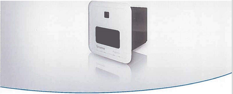
Truma AquaGo@ LP Gas Instant Water Heater
MODEL:
• Truma AquaGo Basic (DLE60B)* *Patent Pending
• Truma AquaGo Comfort (DLE60C)*
• Truma AquaGo Comfort Plus (DLE60CP)*
*PLEASE REFER TO YOUR TRUMA WATER HEATER OWNER'S MANUAL FOR THE MODEL PICTURES*
- Do not store or use gasoline or other flammable vapors and liquids in the vicinity of this or any other appliance.
WHAT TO DO IF YOU SMELL GAS
• Evacuate all persons from the vehicle.
• Shut off the gas supply at the gas container or source.
• Do not touch any electrical switch or use any phone or radio in the vehicle.
• Do not start the vehicle's engine or electric generator.
• Contact the nearest gas supplier or certified service technician for repairs.
• If you cannot reach a gas supplier or certified service technician, contact the nearest fire department.
• Do not turn on the gas supply until gas leaks have been repaired. Installation and service must be performed by a certified service technician, service agency, or the gas supplier.
1. Use with LP gas (propane) only. Butane or any mixtures containing more than 10% butane must not be used. - LP tanks must be filled by a qualified gas supplier only.
2. The nominal gas system pressure must be 10.5 in. wc.
3. Hot water can be dangerous, especially for infants, children, the elderly, or infirm. It can cause severe burns. Therefore: - Never actuate the pressure relief valve (Fig. 1-4) as long as the appliance is still hot. - Never actuate the Easy Drain Lever (Fig. 1-11) as long as the appliance is under water pressure and/or still hot. - Always check the water temperature before entering a shower or bath.
4. How long before hot water causes skin damage?

• The water pressure on the inlet side must be limited to 65 psi (4.5 bar), otherwise internal components of the appliance will be damaged. On (city) water connections with a pressure higher than 65 psi (4.5 bar) a pressure regulator is strongly recommended.
Operating Instructions
Read and follow the "Consumer Safety lnformation" before operating the appliance.

• Water temperatures over 127 °F (52 °C) can cause severe burns or scalding and extreme cases even death.
• Before using the hot water faucet or using the shower, allow the hot water to run until the water temperature no longer increases.
• Test the temperature of the water before placing a child in the bath or shower.
• Do not leave a child or an infirm person in the bath unsupervised.
How the appliance works
The appliance was developed exclusively for use in recreational vehicles (RVs).
The appliance is connected between the vehicle's fresh water supply and its hot water plumbing system.
It is powered by propane and a 12 V power supply. The ventilation grille on the access door allows combustion air to flow into the appliance and exhaust gas to flow out.
When the appliance is switched on, the water will be heated on demand:
• A volume-flow sensor in the appliance detects when the hot water faucet has been opened and the volume flow is greater than approximately 0.4 gallon/min (1.5liter/min). The burner then starts automatically.
• The burner control continuously adjusts the heater output based on volume flow and inlet water temperature, so that the temperature at the hot water outlet is approximately 120 OF (49 o c). A temperature stabilizer is also installed in the appliance to minimize fluctuations of the outlet temperature.
• After some time, the maximum temperature at the faucet or in the shower is reached. The length of time will depend on the model (AquaGo basic, AquaGo comfort and AquaGo comfort plus) and variations in the water plumbing (length of pipes, insulation, circulation line, etc.).
Like in a home shower, a comfortable water temperature at the shower head is reached by mixing in cold water.
• When the volume flow is less than approximately 0.4 gallons/min (1.5 liter/min) and the faucet is closed, the burner is automatically switched off.
The AquaGo comfort and AquaGo comfort plus models are equipped with a circulation pump. The circulation pump as well as the burner are switched on automatically by the control unit in order to keep the water temperature above 102 O F (39 o c) in "COMFORT" mode and 41 O F (5 o c) in "ECO" mode.
NOTICE Risk of damage in frost conditions. Refer to “Operations in frost conditions” on page 13 of the Truma owner’s manual.

Danger of over temperature and toxic exhaust gases!
• Use with the LP gas (propane) only. Butane or any mixtures containing more than 10% butane must not be used.
• Keep the air inlet and exhaust gas outlet free of obstructions. Do not lean any objects against the water heater’s access door or place foreign objects within 2 feet (61cm) of the access door.
Danger of combustion, personal injury and damage to the RV!
• Keep the area around the appliance free from combustible materials, gasoline, and other flammable vapors or liquids.
• Switch the gas supply and the appliance off:
- If anything seems to be out of the ordinary.
- If you smell gas.
- If you move the RV.
- Before entering the gas station. - Before entering a tunnel.
Operating procedures
NOTICE Risk of damage in frost conditions
In frost conditions, ambient temperatures below 39 °F (°C), there is a risk that water in pipes, faucets and appliances could freeze. This can cause considerable damage.
• Before you fill water into appliances and parts that transport water, you must heat the installation area sufficiently so that the water cannot freeze.
Proceed as follows to fill the appliance with water:
1. Close open bypass lines (if present). Insert the water inlet filter or heating cartridge – if removed 2, 7, 9, 11.
2. Turn on fresh water supply or switch on the water pump.
3. Fill the plumbing system.
• Open all the water-release points, e.g., cold and hot water faucets, showers, toilets.
IT IS IMPORTANT THAT YOU BLEED THE WATER SYSTEM BEFORE STARTING THE APPLIANCE.
• Once water flows, the plumbing system is vented. Close the water-release points.
4. Start the appliance as follows:
• Make sure that the LP gas supply is turned on.
• Switch on the 12 V power supply (RV).
• Open the access door (refer to “Opening the access door” on page 8 in the owner’s manual)
• Switch on the appliance at the POWER switch. Refer to “Switching ON the appliance” on page 11 in the owner’s manual.
5. AquaGo comfort /AquqGo comfort plus
• Select the desired operating mode (refer to “Operating modes (control panel)” on page 11 in the owner’s manual.
• Close the access door (refer to “Opening the access door” on page 8 in the owner’s manual.
• There may be a variation between the temperature delivered to from the appliance and the temperature at the faucet due to water conditions or the length of pipe from the appliance.
• The presence of a flow restrictor in the hot waterline may limit the water flow.
6. How to use hot water:
• To obtain the desired water temperature at the faucet or in the shower, mix clod and hot water.
• Particularly when showering, wait until the water temperature has stabilized before entering or allowing other people or animals to enter the shower.
Switching ON the appliance
1. Open the access door
2. To switch on the appliance, switch the POWER switch to one of the two ‘ON” positions.
Both ON positions on the POWER switch have the same function. Choose your preferred position.
• When the green power ON LED 1 is lit, the appliance is switched on.
• If the red error code LED 2 is lit /flashes, there is a fault warning (refer to” APPENDIX A – error codes” on page 37 in the owner’s manual.
AquaGo basic
• The operating mode is set automatically to “BASIC”.
• The appliance is now ready for use.
• Water temperature at the outlet is approximately 120 °F (49 °C)
AquaGo comfort/comfort plus
• The appliance is now ready for using the control panel inside your vehicle. Refer to ‘Operating modes (control panel)” on page 11.
Operating modes (control panel)
AquaGo comfort/AquaGo comfort plus
A control panel to select the operating mode included with the delivery from serial number DLE60X(X)27100000 with the rotary switch you can choose between the following operating modes:
ECO The appliance is now running in energy saving mode.
• Water temperature at the outlet is approximately 120 °F (49 °C)
• Prevention of freezing by using propane gas. The temperature in the appliance is automatically kept above 41°F (5°C).
• During operation, the yellow status LED 3 is lit. Comfort The appliance is now running in a mode that provides rapid availability of hot water.
• Water temperature at the outlet is approximately 120 °F (49 °C).
• Stand by heat. The temperature in the appliance is automatically kept above 102°F (39°C)
• During operation, the yellow status LED 3 is lit.
Stand-by. The appliance is not running in any operation mode.
• The yellow status LED 3 is off.
• To switch the POWER and gas supply refer to “Switching OFF’’ the appliance on page 12 in the owner’s manual.
Switching OFF the appliance AquaGo comfort /AquaGo comfort plus
1. Set the contro Panel to “Off”.
2. Open the access door.
3. Switch off the appliance at the POWER switch -the green ON LED extinguishes.
4. Close the access door.
5. If the appliance is not needed, turn off the gas supply to the appliance.
If you intend to put the RV into storage or turn off the appliance during freezing temperatures, refer to “Winterizing” on page 14 in the owner’s manual.
Operating in frost conditions
Ambient temperatures below 39°F (4°C)
NOTICE Risk of damage in the frost conditions.
In frost conditions, ambient temperatures below 39°F (4°C), there is a risk that water in pipes, faucets and appliances could freeze. This can cause considerable damage.
• If the appliance is not to be used in frost conditions, you must winterize the appliance. Refer to “Winterizing” on page 14 in the owner’s manual.
• Winter operation will not protect the RV’s entire water system. Water lines, faucets, water tanks and the external water valves and the vehicle must be heated separately.
• The RV must be designed for winter use/freezing conditions.
• The water pipes in the RV must be ice free to operate the AquaGocomfort/AquaGo comfort plus in winter. Otherwise, there is no water flow and the appliance does not start.
NOTICE Gas must not be used for heating while the vehicle is in motion. Ask your dealer/vehicle manufacturer about options for heating your RV while driving. Winterizing
NOTICE: Severe damage to the water system components and the appliance
Any damage caused by freezing or an unsuitable winterizing fluid will not be covered by warranty.
• Follow the recommendations if the appliance will be stored under freezing conditions or for an extended period of time.
• Winterize the appliance at the start of the winter season or before traveling to a location where freezing conditions are likely.
If your RV is equipped with a bypass around the appliance, separate the appliance from the water system with the bypass.
Winterizing the appliance
• To winterize the appliance, you must drain all water from the appliance. To do this we advise the following steps:
• Remove the water from inlet filter or heating cartridge. See “Draining the water and cleaning the water inlet filter” on page 15 in the owner’s manual steps 1-8.
• Let water completely drain from the appliance. This can take several minutes.
• Do not insert the water inlet filter or the heating cartridge into the appliance during winter – if the appliance is not used.
• CAUTION Danger of crushing/pinching of fingers when the Easy Drain Lever is closed! Never put fingers between the Easy Drain Lever and latch.
• Close the Easy Drain Lever and the access door.
Once the water has been drained, the appliance is protected against freezing conditions.
Winterizing the RV with a winterizing fluid
Winterizing the RV with a winterizing fluid is only possible with an installed bypass kit (not in scope of delivery)
• Refer to “Connection diagrams on page 31 in the owner’s manual for all letters referred to in the following description.
Winterizing AquaGo basic /AquaGo comfort
1. Close valves A and B.
2. Open valve C
3. Drain the appliance
4. Flush the RV’s water system with a suitable winterizing fluid according to the supplier’s or RV manufacturer’s guidelines.
Winterizing AquaGo comfort plus
1. Close valves A, B and E.
2. Make sure that valve D remains in the closed position.
3. Open valve C.
4. Drain the appliance
5. Flush the RV’s water system with a suitable winterizing fluid according to the supplier’s or manufacturer’s guidelines.
6. Close all faucets (if open).
7. Open valve D.
8. Wait until winterizing fluid has drained. Collect escaping fluid in a suitable vessel.
9. Close valve D.
Rinsing the water system
• You will need about 8 gallons (30 liters) of water to rinse the water system.
• Dispose of (used) decalcification solution in accordance with local laws and regulations.
Tasks within the RV
• Open all water-release points, e.g., hot water faucets, showers, toilets.
• Run the water until the status LED 3 on the control panel goes out.
• Set the control panel to “Off’.
• Close all water release points.
• Turn OFF the water supply or switch OFF the water pump.
• Open a hot water faucet to relieve pressure in the system.
To make sure that the appliance and the water pipes contain no decalcification agent, empty the water system again and refill it.
Tasks outside the RV
• Switch the appliance OFF at the POWER switch (red error code LED 2) flashes before it switches off.
• Drain the water system (refer to “Draining the water and cleaning the water inlet filter” on page 15 steps 1-8 in the owner’s manual.
• Install the water inlet filter. (referring to step 9). Or antifreeze cartridge if electric antifreeze kit is installed.
• Switch ON the appliance at the POWER switch.
• Insert and close the access door (refer to “Closing the access door “on page 9).
You have to switch the appliance off and on to unblock decalcification and enable further operation.
Filling the water system
Tasks within the RV:
• Turn on fresh water supply or switch on water pump.
• Fill the water system.
-Open all water-release points, e.g. hot water faucets, showers, toilets.
-Once water flows evenly, the water system is vented.
-Close the water-release points.
• Before you use the water system and the appliance, check the color of the water at all faucets.
-Slightly red> rinse again.
-Clear -> decalcification is finished.
• Remove the warning signs” Caution decalcification in progress”.