09 Electrical Features
General Information
There are two electrical systems in your motorhome. These are the 12 volt DC (VDC) system and the 120 volt AC (VAC) system. Most standard appliances require the 120 VAC system, while the majority of the lighting systems used in the motorhome use the 12 VDC electrical system.
The electrical power for the 12 VDC system is supplied by the batteries of the motorhome. Those batteries are charged by a power converter. The alternator also charges the batteries when the engine is running.
The electrical power for the 120 VAC is supplied by the power cord when the motorhome is connected to an external power source or when the on-board electrical generator is in operation. The converter/inverter can also supply 120 VAC electrical power (to limited outlets and limited appliances)— the inverter transforms the 12 VDC electrical power from the batteries into the 120 VAC electrical power for the basic appliances.

To connect the motorhome to an external source of 120 VAC electrical power, Tiffin Motorhomes recommends that all of the circuit breakers be in the OFF position, (this is done to prevent any power surge when connecting the motorhome to the external power source), and then unwind the power cord from the electrical compartment located in an external compartment. The standard, flexible, power cord supplied with the motorhome is designed to handle up to 50 amperes. Make sure that the pins in the male end of the plug are oriented correctly so that they match the power cable, and that they are in good condition (i.e., are not bent or damaged).
If there is a circuit breaker switch at the “plug” end of the power cord, that breaker must be turned OFF before making the connection. Insert the plug into the mating outlet, and then turn the circuit breaker ON. Close and lock the electrical compartment door to protect the contents and to keep them clean and dry. Close the cover on the power box, if so equipped, to avoid an unintentional disconnection and to keep the contents clean and dry. Then switch the main breaker to the ON position.
When properly connected, the 120 VAC system provides power to all the 120 VAC circuits and outlets when the main breaker is turned ON.
Spyder Controls System
The 12 VDC system in your coach is controlled by the Spyder Controls Multiplex System. This electronic command center has an easy-to-read touchpad screen (Figure 9-1), that enables you to control features throughout the coach. Through 6 tabs, (home, lighting, battery, thermometer, slide-outs, and settings) this control system enables you to control almost every electronic feature inside your coach. It even enables you to control outside awnings and lights. As shown in the following figure, you are able to view tank levels, lighting controls, water heater controls, temperature, and much more.

For detailed instructions and videos on the Spyder Controls System, visit www.spydercontrols.com

Click on the Customers tab at the top (Figure 9-2). To access text and audio files, use the following information:
Username: Tiffin
Password: Motorhomes
| NOTE: Both username and password are case sensitive. |
Multiplex System
The multiplex system (Figure 9-3) enables you to control circuits from multiple locations in the coach. Each switch enables you to turn a circuit ON or OFF with individual button presses, and provides an indicator light to determine the status of the circuit (ON or OFF).
Additional features of the multiplex system include the following:
• Master Feature (this is only on the control panel located at the entrance door) — Enables you to turn all lighting circuits ON or OFF by pressing a single button labeled Light Master. Pressing the Light Master OFF switch will turn off all the interior lights within the coach. Momentarily pressing the Light Master ON switch will turn on the same circuits that were on when the Light Master OFF switch was pressed. Light Master OFF remembers which lights were on when the switch was pressed and will turn those same lights back on when the Light Master ON switch is momentarily pressed. Holding the Light Master ON switch will turn on all interior light circuits.
• Switch Panel Backlighting — All of the switches are backlit to make the labels easy to read. If you desire to turn the panel lights OFF, a switch is conveniently located at the center of the coach labeled Panel Lights, which enables you to turn the back lighting ON, OFF, or DIM.
• Status LED Indicator — A green LED beside each switch indicates whether the load is ON or OFF. In some cases, certain switches such as Awnings, Compartment Locks, and Generator do not have a status indicator at the switch.

Electrical Cautions

Circuit Breaker Boxes

For the Allegro RED, the location of the 120 VAC and 12 VDC breaker boxes (Figure 9-4) vary depending on your specific floorplan, however, they are located inside the motorhome
The circuit breakers and associated fuses are installed to protect the electrical system of the Allegro RED from any overloads. Do not attempt to change the electrical circuitry or to add appliances yourself.
Please consult an authorized Tiffin Motorhomes Dealership or Tiffin Motorhomes, Incorporated in Red Bay, AL to determine whether any changes you de-sire are appropriate and acceptable.
Please note that the 12 VDC breakers are located in a compartment adjoining the 120 VAC breakers.
120 Volt (VAC) AC Receptacles
Your motorhome is equipped with several 120 VAC receptacles (Figure 9-5) located throughout the interior of the motorhome.
These 120 VAC receptacles are of the “three-prong” variety; the third prong being a grounding pin that provides adequate grounding to protect one from any electrical shock.
For these receptacles to work properly, do not use an adapter, cheater, or extension cord which defeats the function of the grounding pin. For the same reason, never remove or bend away the ground prong or pin from any threeprong AC plug so that it would fit a two-prong AC receptacle (i.e., an ungrounded AC receptacle).
Never operate the Allegro RED if there is an electrical short present, as an electrical short may deliver an electrical shock to anyone coming in contact with the exterior of the unit. If you should feel even the slightest of electrical shock, immediately disconnect the unit from the 120 VAC power source and locate the electrical fault (i.e., typically, it is a break in the grounding circuit).
Do not reconnect the 120 VAC power until after that electrical fault is fixed—the grounding circuit must be continuous from the frame to the distribution panel, to the power cord, and to the earth ground so that electrical-shock protection is realized.

Ground Fault Circuit Interrupt Receptacles
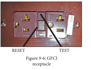
In the kitchen and bath areas, there are 120 VAC GFCI receptacles (Figure 9-6), which provide greater protection against inadvertent electrical shocks.
These specialized GFCI receptacles provide both over-load and short-circuit protection for the user. The electrical receptacles located in the slideout are wired through the kitchen GFCI. The exterior receptacles are wired through the bathroom GFCI. Consequently, if an appliance plugged into a slide-out or exterior receptacle is not working, check for a tripped GFCI in the kitchen or bathroom.
If an appliance plugged into a slide-out or exterior receptacle is not working, check for a tripped GFCI in the kitchen or bathroom.
All GFCI-protected receptacles are marked as such, but only one of them may have two pushbuttons on the receptacle (Figure 9-6). The upper pushbutton is a “test” button, which can be used to assure that the GFCI function is working—all you need do to test this function is to push that upper button:
There will be a momentary “click” and the circuit will be disconnected (i.e., no power is available at the GFCI-protected receptacles).To reset this GFCI breaker, push the lower button (the “reset” button) to restore power to all the GDCI receptacles on this circuit.
These receptacles protect the user from ground faults between an electrically “hot” wire and ground. The GFCI will not reduce the shock hazard if the short is between a neutral and “hot” wire, or two “hot-load” wires. The GFCI should be tested at least once a month. The 120 VAC electrical system must be “on” for the GFCI to be tested. To test the GFCI the reset button needs to be pushed in fully before starting the test. Push the test button; this will cause the reset button to pop out which means that the protected circuits have been disconnected. Push the reset button back in until a “click” is heard—this will re-activate the protected circuit. If the GFCI is working properly, the reset button will remain in the “in” position.
Converter/Inverter
A converter/inverter (figure 9-7)is provided as a standard feature on the Allegro RED. This converter/inverter provides these three basic functions:
1. Convert 120 VAC power into 12 VDC power when 120 VAC is available. The converter will create 12 VDC to charge the house batteries when 120VAC power is available from shoreline or the generator.
2. Invert 12 VDC power into 120 VAC power when 120 VAC is not available. The inverter can create 120 VAC to power the entertainment system (e.g. TVs, Blu-ray player and optional residential refrigerator when 120 VAC power is not available.
3. Transfer 120 VAC power to the inverter loads (e.g. entertainment system, microwave, optional refrigerator and various other 110 outlets) when 120 VAC power is available.
The converter/inverter will transfer or pass 120 VAC power to its loads when plugged into shoreline or running the generator.
The converter/inverter is conveniently mounted in one of the compartments located beneath the motorhome. Do not store items around the inverter as these items could cause accidental electrical short circuits or obstruct the cooling fan leading to overheating.
On the front face of the inverter remote panel (Figure 9-8), there is a green LED to indicate “CHARGING/INVERTING” and a small grey button labeled “POWER ON/OFF.” When the unit is inverting, the green status LED will blink once every second. When the unit is charging, the green LED will light up solid green if the unit is bulk charging, blink once every second when absorb charging, and blink once every eight seconds when float charging. Refer to the manual for your inverter model for more information. The “POWER ON/OFF” button can be pressed and released to turn the inverter on and off. Note that this will not turn off the charging function, or restrict power transfer when converter/inverter is connected to a 120 VAC source.
The “POWER ON/OFF” button is also used to perform a soft reset of the inverter. Before performing a soft reset, disconnect the unit from any 120 VAC source, as leaving it connected during a soft reset may cause damage to the converter/inverter. Press and hold in the button for 15 seconds until the green status LED starts blinking rapidly. Release the button and the LED should go out. Press and release the button to complete the soft reset.
The 12 VDC wiring for the converter/inverter comes from the circuit breaker located underneath the step cover next to the house batteries. Check this circuit breaker if converter/inverter functions are not working.
The 120 VAC wiring for the converter/inverter comes from a circuit breaker in the circuit breaker box. This is the 120 VAC power into the converter/inverter. There is also 120 VAC wiring from the converter/inverter returning to a circuit breaker in the circuit breaker box. This is 120 VAC power out of the converter/inverter used to power the inverter loads. Check these circuit breakers if converter/ inverter functions are not working.
There are two circuit breakers located in the 120-volt circuit breaker box inside the motorhome which are labeled Inverter In and Inverter Out. Make sure these breakers are in the “On” position. The inverter control is located in a cabinet above the driver’s seat. For more information on this feature, consult the Magnum owner’s manual. : Electrical
Electrical Generator
The 8.0 KW electrical generator is conveniently located by opening the front hood of the motorhome. To open hood, use the hood handle located in the first driver's side compartment. (Figure 9-8)
Prior to starting or stopping the generator (Figure 9-9), make sure that all the 120 VAC appliances are turned “off.”
After the generator has been started, wait until the transfer switch has connected before turning “on” any of the appliances.
The generator can be started from either the remote-start switch located on the dash or directly at the generator itself. The hour meter installed on the generator records the number of hours of operation of the generator motor—this elapsed time is needed for observing necessary maintenance schedules on the generator.
For more detailed operating instructions and to determine necessary preventive maintenance schedules and procedures, review the manufacturer’s owner’s manual.


Automatic Transfer Switch
The automatic transfer box switches 120V AC power from the shore or generator to the coach’s main distribution panel. The transfer box has a delay of around three seconds before switching power to the shore, and a delay of around 30 seconds before switching power to the generator.
If the unit is plugged into the shore but there is no power to the coach, then make sure the shore outlet has power. If power is present, this might indicate that the unit is sensing an open neutral condition. Start the generator; if the power is restored, then the shore plug or the outlet might be defective (the neutral line might be broken).
If there is no power to the coach from the shore or generator, then check the generator circuit breaker. If the circuit breakers are not tripped in the generator or the coach, the transfer box might need to be replaced. For more detailed information on the automatic transfer switch, refer to the specific owner’s instructions found in the owner’s information package.

Circuit Breakers
The 12 VDC circuit breakers (Figure 9-10) are located in an external storage compartment.

When the circuit breakers are shut down or electrically tripped, they must be manually reset. These breakers protect various electrical components throughout the motorhome. As needed, manually reset the circuit breaker or breakers as shown in the accompanying figure. When the breaker is tripped, it will be extended outward. To reset it, push the button back in.
Be careful when working around these connections as an accidental electrical short to ground (i.e., momentarily connecting the “positive” or “hot” terminal to any part of the chassis) can be hazardous and harmful. AG6A Control Panel Load List is shown in Figure 9-11.
G6A Control Panel Load List

12 Volt DC (VDC) Receptacles
Your Allegro RED motorhome may be equipped with a 12 VDC receptacle conveniently located inside of the center console (Figure 9-12). This 12 VDC receptacle can be used for providing power to various items, such as cellular phones, personal computers, or portable communications equipment.
This receptacle is usually found on the bulkhead in front of the passenger’s seat so that it is conveniently available to be used by the personnel in the cockpit area. This receptacle accommodates the “cigarette-lighter” type of connector.
This receptacle is usually found on the bulkhead in front of the passenger’s seat so that it is conveniently available. This receptacle accommodates the “cigarette-lighter” type of connector.

USB Receptacles
he Allegro RED is equipped with USB receptacles (Figure 9-13) conveniently located on the front dashboard and in the bedroom area as well as on the passenger console. These ports allow for easy access when charging cell phones, laptop computers, iPods, iPads, or other tablets.

Battery Inspection and Care
The motorhome batteries (Figure 9-14) are located on a sliding tray, which extends from an underneath compartment.
When batteries are not used for extended periods of time, they will gradually lose their electrical charge. Therefore, it is necessary periodically to recharge the batteries to increase the operational lives of the batteries. It is also necessary to check the external condition of the batteries on a regular basis. Look for cracks in the battery case and cover.
Check the vent plugs and replace them if they are cracked or broken. Keep the battery clean. Since accumulations of dirt and acid residue around the battery terminals may provide an electrical path for discharging the battery, the area around the terminals should be cleaned periodically. One can use an old toothbrush and a sparse amount of a diluted solution of baking soda (sodium bicarbonate) and water (distilled or de-ionized, preferred; tap water, acceptable) to clean and neutralize any acidic build-up around the battery terminals. If there is any forming on the top of the battery, this indicates that acidic residues are being neutralized. Rinse the cleaned areas thoroughly with distilled or de-ionized water (tap water is okay, too).
Avoid getting the baking-soda solution into the battery fill plugs to each battery cell; this would drastically reduce the effectiveness of the battery (by neutralizing the sulfuric acid in the battery cells) or, worse, “kill” the battery. Dry the battery cables and terminals to prevent corrosion; to protect those terminals further, use a plastic ignition spray on the terminals. Do not use grease on the terminals, especially on the metal-to-metal connections, as grease may act as an insulator and keep the battery electrical power from entering the cables.
If the batteries are not going to be used for an extended period of time, they should be removed from the Allegro RED and stored in a warm, dry place. IT IS STRONGLY RECOMMENDED that this service be performed by a qualified service technician, as the process is usually too complicated for the average owner to perform. For those who may wish to perform this service themselves, the following procedure is described: Mark the battery cables (“+” sign or “red” for the positive cable; “ - ” sign or “black” for the negative cable) so that they can be properly reconnected again later. These batteries would require periodic recharging to maintain their full charge.
Periodically check the fluid levels in all the cells of the batteries and fill those that are low with water. Don’t overfill the cells; follow the filling directions exactly. This battery checkup should be done on a regular basis to realize the fullest service possible from the batteries over the longest time possible. If the Allegro RED is to be stored for an extended period of time, the 12 VDC battery system should be disconnected—this procedure will prevent unnecessary drain and corrosion of the batteries and their terminals.

House Battery Disconnect Panel
The house battery disconnect panel is located in the cargo storage area on the driver side. Along with the inverter switch and several breakers, the rotary switch labeled “House Battery Master Switch” (Figure 9-15) can disconnect the house batteries when the vehicle is in storage for long periods of time.
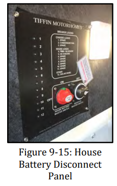
Rotating this switch disconnects the house batteries only, not the engine batteries. This feature is designed to disconnect all 12 VDC circuitry from the batteries and prevent them from being drained during storage.
Engine Battery Disconnect Panel
The engine battery disconnect panel is located in an outside rear compartment of the passenger’s side, above the engine batteries.

When the Allegro RED is removed from storage, rotate the upper left-hand switch to reconnect the 12 VDC circuitry to the coach batteries and rotate the upper right-hand switch (Figure 9-16) to reconnect the house battery. This will make the 12 VDC systems active again.
Turning the knob to the red disconnect position will turn off all power to the ignition side of the coach. If the coach is to be stored for an extended period of time, or if the engine is being serviced, it is recommended that the disconnect be in the “Off ” position.
12 Volt DC Disconnect Switch
For routine short-term use, there is a 12 VDC disconnect switch (Figure 9-17) on the switch console located in the stairwell of the Allegro RED. This switch can be used to disconnect the “house” battery from most of the 12 VDC circuits in the motorhome so there is no inadvertent drain on the battery.

Auxiliary Start Switch
The auxiliary start switch (Figure 9-18) is located on the switch panel to the left of the steering wheel in front of the driver’s-side console box.

This switch connects the motorhome coach batteries to the chassis batteries—this allows the chassis batteries to “borrow” power from the coach batteries to assist in starting the engine.
If the chassis batteries cannot start the engine by turning the ignition key, hold down the battery-boost switch for at least 60 seconds and retry starting the engine.
When attempting to use the auxiliary start switch function, Tiffin Motor Homes recommends that you press and hold the switch for about 60 seconds before trying to start the engine. This gives the two sets of batteries (house and chassis) a chance to equalize before engaging the starter. The multiplex system that controls most chassis functions will need to reach optimal voltage range to ensure proper operation as well.
Seven-Pin Towing Connector

Your Allegro RED is equipped with a standard, 7-pin connector near the towing hitch at the rear of the motorhome to supply the necessary circuitry to control a towed vehicle.
The connector wiring is shown in the accompanying diagram (see Figure 9-19).
The wiring of that connector is shown in the accompanying diagram (Figure 9-19).
Make sure that any cable from the vehicle to be towed is wired correctly to mate properly with the connections shown in the connector. If in doubt about proper wiring, have a qualified service technician prepare and install the necessary cable to mate with the 7 pin connector on the motorhome to ensure proper operation subsequently when any vehicle is actually towed by the motorhome.
When the towed vehicle is uncoupled from the motorhome and the cable is disconnected from the 7 pin connector, be sure to close the spring-hinged cover plate on the connector to protect the contact pins from dirt or debris. In a similar manner, protect the cable end from similar damage, weather, or debris— one such method could be to place the connector end in a heavy-gauge plastic bag (e.g., polypropylene, polyethylene, etc.) and secure the bag tightly around the cable with a stout elastic band or tape and then mount the secured cable in a manner to keep it both from mechanical damage and water intrusion.
When the towed vehicle is again coupled to the motorhome through the towing hitch and the cable is again connected to the 7-pin connector, make sure the resultant connection is tight and solid so that the connection does not jar loose during use. Several supplemental methods to secure that connection have been used; some of which include securing the connection with a strong rubber band or with Velcro-type fasteners to provide a supplemental mechanical backup to the actual electromechanical connection. If a conversion adapter to convert the round, 7-pin connector to a flat, 4-pin connector is needed, purchase one from any RV after-market store.