05 Major Appliances
LP/Gas Refrigerator
Your coach may be equipped with a standard LP/gas refrigerator. When this refrigerator is in the “LP gas” mode, make sure that the main LP gas valve is in the “on” position before attempting to start the refrigerator. Please note that the refrigerator is equipped with a semi-automatic energy selector (AES) control system which can set automatically to switch between a 120- volt AC system or a LP-gas operation system.
A 12-volt power supply (e.g., 12 VDC system of the motorhome, auxiliary battery, converter, or motorhome engine battery) is required for proper operation of the electronic control panel. For electrical operation of the refrigerator, either the external electrical power line must be connected to the motorhome or the on-board electrical generator must be running to provide the necessary 120-volt AC power. To operate the refrigerator in the LP-gas mode, the main LP gas valve must be open.
- To turn ON the refrigerator, press the main power ON/OFF button (ON position). Select operation mode (Auto or Gas). If necessary, adjust the thermostat by pressing the temperature selector button.
- To turn OFF the refrigerator, press the main power ON/OFF button (OFF position). The refrigerator can be shut off while in any mode of operation by pressing the main power ON/OFF button. This shuts off all DC power to the refrigerator, including the interior light. If the refrigerator will not be in operation for weeks, it should be emptied, defrosted, cleaned and the doors left ajar. The ice trays should also be kept outside the cabinet.
- Place a small level on the bottom of the refrigerator to make sure it is level before its operation.
For further operating and maintenance instructions, refer to the operating booklet found in the Owner’s Information Package.


Residential Refrigerator (Optional)
Some coaches contain the optional 110 volt style residential refrigerator (Figure 5-2), which is powered from an outside source or from the unit’s generator or inverter, which uses a 12 volt battery power supply.

This unit operates as most home refrigerators do.
| NOTE: While traveling, the refrigerator will be powered by the inverter. |
For further operating and maintenance instructions, refer to the operating booklet found in the Owner’s Information Package.
| NOTE: While traveling, the 12 V battery is charged by the engine alternator. |
Ice Maker
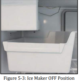
Your ice maker (Figure 5-3), is equipped with an automatic shut off. As ice is made, the ice cubes will fill the storage tray, raising the shutoff arm to the OFF position. Do not force the wire shut off arm up or down.
- To turn ON the icemaker, lower the wire shutoff arm.
- To turn OFF the icemaker, lift the wire shutoff arm to the OFF position (arm up) until it clicks.
| NOTE: The ice maker must have RV antifreeze cycled through it for proper winterization. |
Microwave Oven
The Allegro RED contains either a microwave oven (Figure 5-4) or an optional convection microwave. All microwave ranges operate on 120-volt AC electrical power, supplied either by the external electrical hook-up or by the on-board electrical generator in the motorhome.
Touchpad controls are used for operating the convection microwave (i.e., cooking temperature, mode, power level, and cooking time). For basic operating instructions, care, and maintenance for the proper use of the microwave, refer to the specific manual in the Owner’s Information Package.

Air Filtration Fan

In the Allegro RED, the “exhaust” or air-filtration fan (Figure 5-5) is built into the microwave and its function is to filter the air and exhaust to the outside.
The filtration fan must be used whenever cooking is performed to filter any airborne cooking residues and heated air.
The filtration system can be used as supplemental filtration of other odors and gases including tobacco smoke, candle fumes, and related vapors. It contains filters, which can be removed and cleaned or replaced to ensure normal operation. Consult the particular owner’s manual contained in the Owner’s Information Package.
Optional Oven and Optional Cooktop
The Allegro RED may be equipped with a standard recessed three burner cook top or it may have an optional, three-burner, recessed cook top with oven.
Do not attempt to adjust the oven pilot light as it has been factory-adjusted and factory-set. To extinguish the oven pilot light when use of the oven is concluded, push inwards on the oven control knob and turn that knob clockwise (CW) to the “off ” position.
It is wise to have a qualified service technician periodically check the entire LP-gas distribution system in the motorhome. Scheduling such an inspection annually would be a recommended, preventive-maintenance routine for each motorhome owner.

Lighting top burners with spark ignition
A. Turn the burner knob counter-clockwise to “ON” or “LITE”
B. Turn the Spark knob clockwise one click. If the burner fails to light, continue turning the SPARK knob clockwise until the burner lights.
C. To extinguish the top burner flame, turn the burner knob clockwise to OFF.
Lighting the oven pilot
A. Push in oven control knob and rotate counter-clockwise to PILOT ON - PUSH/HOLD.
B. Push the knob in and hold it in while holding a lit match under the oven pilot located near the back of the oven under the broiler shelf and to the right of the oven burner
C. Continue to hold the oven control knob in for five seconds after pilot is lit.
D. Set the oven control knob to PILOT PUSH/HOLD to maintain the pilot flame. The oven and broiler are now ready for operation.
E. To extinguish the pilot, push the control knob and rotate clockwise to OFF.
Lighting the oven burner
A. Light the oven pilot as described under “Lighting the oven pilot”
B. With the oven control knob set to PILOT PUSH/HOLD, push in and rotate the knob counter clockwise to the desired temperature setting or to BROIL. The oven will pre-heat in about 15 minutes.
C. To extinguish the oven burner, rotate the knob clockwise to PILOT PUSH/HOLD. The oven pilot will remain lit.
D. For complete shutdown, push in and rotate the knob clockwise to OFF.


Water Heater


Before the water heater (Figure 5-7) is used, fill the fresh-water system and purge the water lines to and from the water heater by opening all the hot-water faucets until water steadily flows from each one and no “spurting” or “hissing” sounds are heard.
The water heater uses either the LP gas system or the 120- volt AC electrical system to operate the heater. Proper and safe operation of the water heater requires that all safety information provided in the owner’s manual be read and understood before placing the water heater in service. Take the time to become familiar with this manual (provided in the Owner’s Information Package).
The water heater is designed for operation either with LP gas or 120-volt AC electricity.
NOTE: When you turn “on” the switch for the water heater the middle red button will light up. It will go o aer several seconds—this means the water heater is lit. However, if the light stays illuminated, then that means the water heater has not ignited.
LP Gas – Electronic Ignition Operation
1. On the Spyder control panel, press the last icon on the left side of the panel. (It looks like a thermometer). This will bring up the controls for the water heater.
2. Press the touch panel button that says “Gas Water Heater” to the on position. The water heater will attempt to light. If it takes longer than 15 seconds, a “FAULT” message will appear. Make sure the "Gas Water Heater" button reads “Off” and wait 5 minutes.
3. Repeat Step Two until water heater is lit.
4. For a complete shut-down and also before any servicing:
a. Turn the “Gas Water Heater” switch to the “off” position.
b. Remove the red wire from the left-hand terminal of the ECO switch (ECO to valve) on the water heater.
5. If the water heater fails to operate because of high water temperature, the heater will go into a lockout condition (screen will read "FAULT"). When the water eventually cools, reset the system by turning the switch to the “off ” position for at least 30 seconds, and then turn the switch back “on.”
6. If a lockout condition persists, contact your authorized dealer.
120-Volt AC Electrical Operation
1. For electrical operation, use the "Electric Water Heater" button found on the Spyder master control panel.
2. Completely fill the water heater with water and purge the hot-water lines of any trapped air.
3. Turn the Water Heater switch “on.” NOTE: Turning the power “on” to the water heater without having previously covered the water-heating element with water may burn out the element and void the warranty.
4. After awhile, check the water heater for proper operation; the water temperature should be approximately 140°F (60°C).
5. If the manual-reset, high-temperature-limit switch should trip the circuit breaker; reset the switch by depressing the reset button--use a pencil or other non-metallic object to depress the reset button. If the high-temperature-limit switch should again trip the circuit breaker, contact an authorized service technician or an authorized dealer.
6. Both the electrical and gas operations of the water heater may be used simultaneously to reduce recovery time of heating water up to desired temperature.
For general maintenance of the water heater or specific information about select steps in operating the water heater, please refer to the owner’s manual for this appliance contained in the Owner’s Information Package.

Water Heater Storage
If the motorhome is to be stored during the winter months, the water heater (Figure 5-8) should be drained to prevent damage caused by freezing water contained in the water heater.
To drain the water heater, first turn “off ” all electrical power, turn “off ” the LP gas going to the water heater, then turn “off ” the water pump. Open both the hot- and the cold-water faucets to drain the water lines and open the drain on the water heater to drain the entire system.
When re-activating the water heater after the motorhome is taken out of storage, make sure that the entire water system, including the water heater, has been filled with water and the lines have been purged of any entrapped air before relighting the water heater. Failure to do so may allow the water-heating element to be turned “on” before it is immersed in water; thereby, causing the premature failure of the heating element and voiding the warranty.

Pressure Relief Valve
The relief valve for over-pressure and over-temperature conditions is located on the exterior of the water heater. This valve will operate if the water temperature reaches or exceeds 210°F or if the water pressure reaches or exceeds 150 psig.
Since the water system in the motorhome is a closed system when all water valves are shut, the water heating cycle can raise the temperature and, consequently, the pressure, of the water in the water heater; thereby realizing pressure increases approaching 150 psig.
Should this pressure (i.e., 150 psig) be reached, the pressure-relief valve will begin “weeping,” that is, there will be minor dripping or leakage from that valve until the pressure drops below 150 psig, at which time the pressure-relief valve will reseat itself and restrict the water flow. This is normal operation and should not be a cause for alarm. Do not obstruct or block the pressure-relief valve in any way, as this would keep the valve from functioning normally and protecting the hot water system.