Go Power: Solar Panel Controller User Manual
Overview
The 30A RV-C MPPT solar controller is an advanced dual bank controller with RV-C communication for smart RV systems. As an MPPT Solar controller it continuously monitors the solar panel’s generating power and tracks the maximum power point, enabling the system to charge the battery with maximum power all the time. It is designed to be used in off-grid solar photovoltaic systems to coordinate operation of the solar panel, battery, functioning as the core control unit in off-grid photovoltaic systems.
With comprehensive electronic fault self-detecting functions and powerful electronic protection functions built inside the controller, component damage caused by installation errors or system failures can be avoided.
This product features an optional LCD remote which displays the operating status and allows the control of configurable parameters. Users can conveniently check parameters using the buttons and modify control parameters to cater to different system requirements. The optional remote also includes Bluetooth communication that allows a smart phone to be conveniently used to perform all the same tasks that the LCD remote can.
Features
- Advanced multi-peak tracking technology. When the solar panel is shadowed or part of the panel fails resulting in multiple peaks on the I-V curve, the controller is still able to accurately track the maximum power point
- Built-in maximum power point tracking (MPPT) algorithm significantly increases energy utilization efficiency of the photovoltaic system, (up to 30% higher than traditional PWM charging)
- MPPT tracking efficiency of up to 99.9%
- Power conversion efficiency of up to 98%
- Lithium battery reset capability allows a BMS protected over discharged battery to be automatically recovered without having to disconnect the battery
- Presets for multiple battery chemistries, including LiFePO4, Flooded, Gel and AGM
- Supports user customized charge parameters
- Current-limited charging mode. When the power of solar panel is too large and the charging current is higher than the rated value, the controller automatically reduces the charging power so that the solar panel can operate at the rated charging current.
- Features LED fault indicators, which can display abnormal information, helps users to quickly identify system faults.
- Historical data storage function is available
- Minimal derating up to the maximum operating temperature
- Dual-battery management
- Temperature compensation and automatic adjustment of charge parameters help to improve battery life.
Appearance

| NO. | NAME | NO. | NAME | |
| 1-5 | Instance Indicators | 13 | Connection Terminals (PV-) | |
| 6 | LED Indicator (BAT2) | 14 | Connection Terminals (PV+) | |
| 7 | LED Indicator (BAT1) | 15 | Port for external temperature sensor | |
| 8 | LED Indicator (PV) | 16 | Canbus Communication Port | |
| 9 | Connection Terminals (BAT2-) | 17 | RS485 Communication Port | |
| 10 | Connection Terminals (BAT2+) | 18 | Setup Key | |
| 11 | Connection Terminals (BAT1-) | 19 | Installation Hole | |
| 12 | Connection Terminals (BAT1+) |
Maximum Power Point Technology
Maximum Power Point Tracking (MPPT) is an advanced charging technology that more efficiently harvests power from solar panels in all conditions. It does this by continuously tracking the I-V curve of the solar array and modifying operating conditions to maximize output power. The graph below shows the MPPT point compared to a traditional PWM charger, which always runs the solar array at a voltage close to the battery voltage.
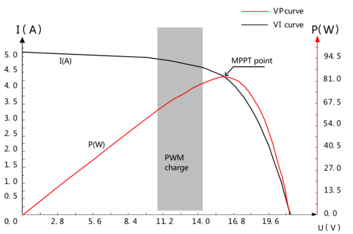
Due to differences in ambient temperature and light conditions, the maximum power point often changes. The MPPT controller can adjust parameters according to quickly changing conditions to keep the system near to its maximum working point. The whole process is fully automatic and does not require any adjustments or interference by users.
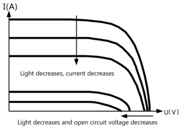
The graph below shows how the IV curve of a solar panel changes with varying sunlight conditions.
The graph below shows how the IV curve of a solar panel changes with varying temperatures.

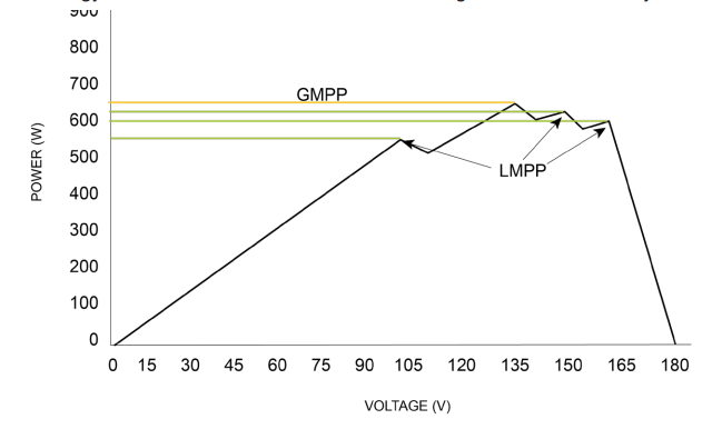
In partially shaded conditions there can also be multiple peaks in the P-V curve that can confuse an MPPT algorithm. Shown in the diagram below is a series string of solar panels.

A corresponding graph below shows lower maximum power points (LMPP) and the greater maxim power point (GMPP) that will result in maximum energy transfer. The GP-RVC series has a smart algorithm that will always choose the right peak.
Charging Stages
Maximum power point tracking is used to charge the batteries with the highest current possible, but this is only part of the equation. A battery cannot be charged at maximum power all the time for safety reasons, so multiple stages are used.
These stages include: bulk, absorption, float and, for some types of batteries, equalization as indicated below.

STAGE 1: Bulk
- In quick charge stage, the battery voltage has not yet reached the set value of full charge voltage (i.e. equalizing/boost charge voltage) and the controller will perform MPPT charging, which will provide maximum solar energy to charge the battery. When the battery voltage reaches the pre-set value, Stage 2 charge will start.
STAGE 2: Absorption
- When the battery voltage reaches the absorption voltage, the controller will perform constant voltage charging. This is no longer MPPT charging, and the charging current will gradually decrease with time.
STAGE 3: Float
- Float charge is conducted following the absorption charge stage. The controller will reduce the charge current to a small amount in order to reduce sulfates on the battery plates or to allow a lithium battery to balance it’s cells. If the load exceeds this small current the battery voltage will start to decrease until it reaches the recharge voltage. When the battery voltage falls below the recharge voltage, the controller will switch back to bulk charging.
STAGE 4: Equalize
 |
Warning: Risk of explosion! Equalizing vented lead-acid battery may generate explosive gases. So, the battery compartment must be well ventilated. |
 |
Caution: Damage of device! Equalization can increase the battery voltage to levels that may damage sensitive DC loads. It is necessary to verify that the allowable input voltage of all system loads is greater than the equalizing charge set value. |
 |
Caution: Damage of device! Over charge and excessive gas evolution may damage the battery plates and cause active substances on the battery plate to come off. Equalizing charge may cause damage if voltage is too high or time is too long. Please carefully check the specific requirements of battery used in the system. |
Certain battery types benefit from regular equalizing charge, which can stir electrolytes, balance battery voltage, and complete the chemical reaction. The equalize charge increases the battery voltage above a standard voltage, causing vaporization of battery electrolyte. By default, this happens every 30 days for flooded batteries.
Recharge
After the battery is completely charged the charging cycle completes and the battery is allowed to slowly discharge until it reaches the charge return voltage at which point a new charge cycle is initiated.
Charge Parameters for Various Battery Types |
|||||
| Parameter | Gel | AGM | Flooded | LifePO4 | Custom |
| High Voltage Disconnect | 16.0 / 32.0 V | 16.0 / 32.0 V | 16.0 / 32.0 V | 14.6 / 29.2 V | 8..32 V |
| Equalize Voltage | 14.9 / 29.8 V | 8..32 V | |||
| Bulk-Absorption Voltage | 14.1 / 28.2 V | 14.4 / 28.8 V | 14.4 / 28.8 V | 14.4 / 28.8 V | 8..32 V |
| Float Voltage | 13.7 / 27.4 V | 13.7 / 27.4 V | 13.7 / 27.4 V | 14.0 / 28.0 V | 8..32 V |
| Recharge Voltage | 13.2 / 26.4 V | 8..32 V | |||
| Over-Discharge Return Voltage | 12.8 / 25.2 V | 12.8 / 25.2 V | 12.8 / 25.2 V | 12.2 / 24.4 V | 8..32 V |
| Under-Voltage Warning Level | 12.0 / 24.0 V | 8..32 V | |||
| Over-Discharge Voltage | 11.0 / 22.0 V | 8..32 V | |||
| Discharge Limit Voltage | 10.5 / 21.0 V | 8..32 V | |||
| Over-Discharge Time Delay | 5 Seconds | 0..120 seconds | |||
| Equalize Duration | 120 minutes | 0..600 minutes | |||
| Absorption Duration | 120 minutes | 120 minutes | 120 minutes | 120 minutes | 10..600 minutes |
| Equalize Interval | 30 Days | 0..250 days | |||
| Temperature Compensation Factor | -24 mV/°C | -24 mV/°C | -24 mV/°C | 0..-30 mV/°C | |
Dual Battery Charging
The GP-RVC-30-MPPT has two battery outputs: BAT1 and BAT2. The solar controller will prioritize BAT1 at all times to ensure it is always charged as much as possible. After BAT1 has completed absorption charging excess power will be used to charge BAT2. The intention here is to maintain the house battery on an RV to be the highest state of charge possible and then top up the starter battery if needed.
The intended wiring for a motorized RV is shown below.

The detailed charging prioritization is shown in the flowchart below.

Product Dimensions

Specifications
| Item | Parameters |
| Battery Voltage Range | 8V – 32V |
| Max Charge Current | 30A |
| Conversion Efficiency | ≤98% |
| MPPT Tracking Efficiency | >99% |
| Max Panel Input Voltage | 100Voc |
| Max PV Power Input | 600W@12V / 1200W@24V |
| No-Load Loss | <10mA |
| Grounding | Negative |
| Operating Temperature | -35 to 45°C |
| Storage Temperature | -35 to 75°C |
| Humidity | 95% N.C. |
| Battery Type | Lead Acid (AGM, GEL, Flooded), LiFePO4 |
| Max Wire Gauge | 8 AWG |
| Dimensions (H x W x D) | 3.15” x 7.78” x 5.5” |
| Weight | 3.14lbs (1.42kg) |
| Water Ingress Protection | IP32 |
| Altitude | < 3000m |
| Protection |
Solar/battery reverse polarity Solar/battery over voltage Solar/battery short circuit Over temperature |
LED Indicators
LED Identification

PV Indicator (1)
| LED Pattern | Status |
| Off | Night Time |
| Single Flash | Day Time |
| Steady On | MPPT charging |
| Fast Flash | Absorption or Equalize |
| Slow Flash | Float Charging |
Battery Indicator (2) (3)
| LED Pattern | Status |
| Off | No Battery |
| Fast Flash | Battery over voltage |
| Slow Flash | Battery over discharged |
| Steady On | Battery status is ok |
Installation
Tools and Materials Needed
- Screwdriver
- Drill
- Multimeter
Installation and Wiring
STEP 1: Choose and Installation Location
The following things should be considered when choosing an installation location for GP-RVC-30-MPPT controllers.
- The controller should be installed indoors where it is safe from water or condensation
- Avoid installing the controller in direct sunlight
- Mount the controller to a non-flammable surface •
- For best thermal performance mount the controller vertically with power terminals facing downward, this will encourage natural convection through the heat-sink and keep it cooler
- There should be at least 6 inches of air gap above and below the controller for the natural convection to occur effectively

- Locate the controller as close to the battery as possible (but not directly above the battery to prevent potential damage due to gassing of the battery), this will keep the battery wires short and prevent voltage drop
- Ensure any enclosed space where the controller is mounted is well ventilated, this will prevent heat buildup that could lead to derating of the controller
STEP 2: Mark the Mounting Position according to the Mounting Dimensions of the Controller
First, place the controller at a proper position and use a marking pen to mark the mounting points. Drill 4 mounting holes of the appropriate size at the 4 marks. Fix screws into the upper two mounting holes.
STEP 3: Fasten the Controller
Align fixed holes of the controller with the two pre-fixed screws and hang the controller up. Then fix the lower two screws.
STEP 4: Wiring
Wiring and installation must comply with national and local electrical code requirements. The wire from the solar array most commonly enters the RV through the fridge vent on the roof or by using the Go Power! Cable Entry Plate (sold separately) that allows installers to run wires through any part of the roof. PV connections should connect directly to the controller.
Note: Positive and negative battery connections must connect directly from the controller to the batteries and positive and negative PV connections must connect directly from the solar array to the controller. Wires that are as short as possible and adequately sized (see table below) should always be used. Use of a positive and/or negative distribution bus that is properly sized is recommended between the controller and battery – do not stack wires on the battery terminals.
| PV Max Input Current | PV Wire Diameter (MM2/AWG) | Rated Charge Current | Battery Wire Diameter (MM2/AWG) |
| 30A | 8/8 | 30A | 8/8 |
We recommend the wiring sequence shown below.

Note:
- The battery fuse should be installed as close as possible to the battery terminal. The recommended distance is not more than 150mm.
- The battery temperature will read 25°C (fixed value) when the controller is not connected to a remote temperature sensor.
RV-C Instance Number
RV-C Instance Number Identification
The RV-C instance of an individual controller can be identified by the 5 LEDs on the controller shown below.

Changing the RV-C Instance Number
The instance of the solar controller on the RV-C network can be configured using the SET button and LEDs. Up to 5 unique instances are supported. To change the instance follow these steps:
- Hold the SET button down for approximately 3 seconds until one of the LEDs starts flashing.

- Press the SET button to change instance until the LED for the desired instance is flashing.
- Press and hold the SET button for approximately 3 seconds to lock in the setting.
Parallel Controller Setup
This section outlines the procedure for setting up multiple GP-RVC-30-MPPT controllers in parallel to charge the same battery. These instructions are intended to provide basic steps to configure controllers in parallel prior a pending update to the manual that will include this information
Installation and Wiring
The following installation is used to connect up to five GP-RVC-30-MPPT solar controllers in parallel to charge the same one or two battery banks. Below is an example of the largest system possible. The controllers communicate with each other using the parallel communication cable and the remote shows the status of all controllers when plugged into controller 1 which is the master.

Note: Before starting a parallel controller system setup, please check the firmware version of each controller and check that the firmware version is 2.0 or above to ensure that your solar controllers have parallel support. The firmware version can be checked by short pressing the enter button and scrolling to the bottom.
STEP 1: Install the controllers side by side with no more than 3” of gap between the controllers as shown in the image below. This is so the parallel communication harnesses can reach between controllers.

STEP 2: Wire battery power to the controllers first, then solar power. The LED lights on the solar controllers should come on as shown below:

If one battery is connected the LEDs will look like this:

STEP 3: Connect the remote display to each solar controller and set the battery type. This is accomplished by pressing and holding the “ENTER” button until the following settings screen is displayed.

Navigate to the “B1 Type” using the up/down arrows, press enter, use the up/down arrows to select battery type and then press enter. It is not necessary to change any other parameters are unless there are specific requirements for charging your battery that are different from the default parameters.
Note: This needs to be done for each parallel controller individually.
Step 4: Change the instance number of each controller to be unique. The instance number is indicated by the 5 LEDs shown below

The instance of the solar controller can be configured using the SET button and LEDs. To change the instance follow these steps:
- Hold the SET button down for approximately 3 seconds until one of the LEDs starts flashing.

- Press the SET button to change instance until the LED for the desired instance is flashing.
- Press and hold the SET button for approximately 3 seconds to lock in the setting.
STEP 5: Connect parallel cables between controllers by connecting to the “RVC” port on the front of the controller.

There are two different parallel cables: the main cable and the expansion cable:
- Main
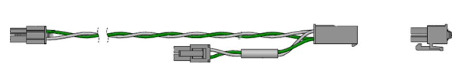
- Expansion

The main harness comes with a removable terminating resistor. If your system uses two controllers, then only the main harness is required. If more than two controllers are required, then one expansion cable is used for each additional controller. The removable terminating resistor should be moved to the last controller.
STEP 6: Move the remote to controller with instance number one. The display should change to have one single number on the top as shown in the image below. Your parallel controller setup is now complete.

RV-C Remote
Bluetooth® Enabled GP-RVC-R Remote
Conveniently set and view essential charge information. The GP-RVC-R is a surface mounted remote display for GP-RVC-MPPT photovoltaic (PV) charge controllers. The GP-RVC-R shows the charge current to the battery and battery voltage.
- View operating status in real-time
- Bluetooth® ready with the Go Power! Connect app
- No need for external power supply
- Identifies and displays controller parameter data of GP-RVC-MPPT series, including:
- voltage
- current
- total charge/discharge
- min/max voltage
- 5-year warranty

Limited Warranty
Go Power! warrants the GP-RVC-R for a period of five (5) years from the date of shipment from its factory. This warranty is valid against defects in materials and workmanship for the five (5) year warranty period. It is not valid against defects resulting from, but not limited to:
- Misuse and/or abuse, neglect or accident
- Exceeding the unit’s design limits
- Improper installation, including, but not limited to, improper environmental protection and improper hook-up
- Acts of God, including lightning, floods, earthquakes, fire, and high winds
- Damage in handling, including damage encountered during shipment
This warranty shall be considered void if the warranted product is in any way opened or altered. The warranty will be void if any eyelet, rivets, or other fasteners used to seal the unit are removed or altered, or if the unit’s serial number is in any way removed, altered, replaced, defaced, or rendered illegible.