Dometic Sealand 4310 Toilet Owner's Manual
Toilet Model Identification
The model identification label is located on the inside wall of the toilet under the access cover. It will show the model number and serial number.

Ordering Parts
Dometic is ready to assist you in the event service is required. Before calling, please have the following information available. Your cooperation in having this information ready is appreciated and allows us to better meet your needs. Please refer to the Parts Distributor list in the Customer Service section.
- Toilet Model Number
- Serial Number
- Part Number, Description and Quantity (see separate Parts List)
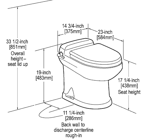
Toilet Dimensions
Installation Instructions
System Requirements:
- 4 GPM (15 lpm) or larger water pump.
- 1/2-inch (12.7 mm) water line terminating in 1/2-inch MPT fitting (to connect to toilet water supply hose).
- 4-bolt floor (closet) flange. SeaLand flanges available include 3-inch spigot, socket, MPT, or 45-degree swivel socket.
- 12 VDC through 2-amp fuse or circuit breaker. Use 14-gauge stranded copper wire.
| Important: If replacing an existing gravity-discharge toilet, make sure the center of the existing discharge flange is at least 11-1/4 inches from the back wall, then proceed to Step 5 for proper positioning of water line and electrical wiring. |
- Step 1: Carefully unpack the toilet bowl, rear access lid and floor flange adapter. CAUTION: HANDLE THE VITREOUS CHINA TOILET AND ACCESS LID WITH CARE. SET THE LID IN AN AREA WHERE IT CANNOT BE BROKEN. PLACE LID ON TOILET ONLY AFTER TOILET INSTALLATION IS COMPLETE.
- Step 2: Position the china bowl in the space intended. Confirm that adequate clearance is available for using the flush handle and opening the seat and lid.
- Step 3: Mark the floor at the rear corners of the toilet bowl (fig. 1). Measure the distance between the two marks and divide by 2 to find the toilet centerline. Mark the floor at the rear wall for the centerline.
- Step 4: Place a carpenter’s square against the back wall, and draw a center line on the floor at least 14 inches (356 mm) long (fig. 2). Mark the centerline for the floor flange at 11-1/4 inches (286 mm) from the wall (fig. 3).

- Step 5A: For through-the-floor water line and electrical wires, mark another centerline 6 inches (152 mm) from the back wall (fig. 4).

- Step 5B: For through-the-wall water line and electrical wires, mark a centerline 8 inches (203 mm) up from the floor centerline (fig. 5).

- Step 6: Make a 4-3/4 inch (121 mm) diameter hole (for most floor flanges) or a 5-1/8 inch (130 mm) diameter hole (for swivel joint floor flange) at the centerline mark furthest from the wall. Make a 1 inch (25 mm) hole at the mark closer to the wall for the water line and electrical wires (fig. 6).

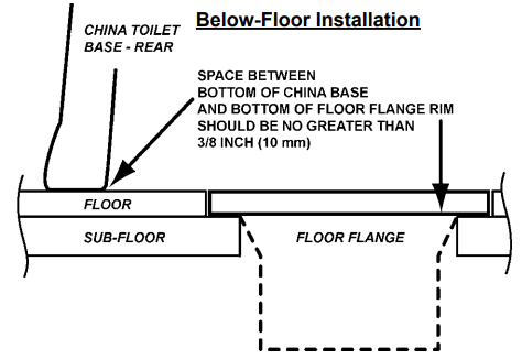
| Important: The preferred floor flange installation method is to mount the floor flange directly on the finished floor. However, if the bottom of floor flange and bottom of china toilet must be mounted at different heights, the floor flange must be mounted within 3/8 inch (10 mm) of the bottom of the toilet (see illustrations in next column) or leakage may result. |
 |
 |
- Step 7: Insert floor flange into larger hole and secure to the floor with #12x3/4-inch long flat head wood or sheet metal screws (fig.7).

- Step 8: Route 1/2-inch (13mm) PEX tubing through the smaller hole and install a PEX 1/2-inch MPT fitting (fig. 8).

- Step 9: WITH THE ELECTRICAL POWER OFF, route #14 gauge stranded copper wire from 12 VDC ground and positive 12 VDC from the fuse panel through a 2-amp fuse or circuit breaker. Leave at least 12 inches (305 mm) of wire for connecting to toilet (fig. 9).

- Step 10: Connect the holding tank to the bottom of the discharge flange.
- Step 11: Slide the four T-bolts into the slots of the floor flange. Install the flange gasket over the T-bolts (fig. 10).

- Step 12: Install floor flange adapter with words “THIS SIDE UP” facing up. Tighten adapter to floor flange using four flat washers and hex nuts. Tighten in criss-cross pattern (fig. 11).

- Step 13: Temporarily set the toilet in place on the floor flange (fig. 14).

- Step 14: Mark the holes for the two toilet mounting bolts (fig. 15).

- Step 15: Pick up toilet and set aside. Drill 3/16-inch pilot holes in the floor (fig. 16).

- Step 16: With toilet close to floor flange, connect flexible water supply hose to the water line fitting (fig. 17).

- Step 17: Connect the positive (+) 12 VDC wire to the red power wire that's connected to the toilet base. Connect the negative (-) 12 VDC wire to the black wire (fig. 18).

- Step 18: REMOVE RED CAP FROM MIDDLE OF FLANGE ADAPTER BEFORE FINAL TOILET INSTALLATION.
- Step 19: Set the toilet in place (fig. 19) and secure to floor with the #14x2-1/2 inch long lag bolts (fig. 20). Install decorative bolt caps by pushing them onto bolt heads (fig. 21).

- Step 20: Place the rear access cover on the back of the toilet. Press down firmly to seat the fastening strips.
- Step 21: Turn on electrical power and water to toilet. Lift flush handle and fill toilet bowl with water. Wait one hour, then inspect the floor around and under the rear of the toilet for leaks or dampness. If no leaks are present, toilet is ready for operation.
Important Information before Operation
- Fill freshwater tank and add deodorant to holding tank through toilet bowl.
- Make sure all guests understand the operation of the toilet system. 4300 models: Follow instructions below. 4400 models: "Add Water" and "Flush" are clearly marked on the remote switch. See more information below.
- Shut off the toilet system before servicing and do not leave the vehicle with toilet system circuit breaker on.
- Never use drain openers, alcohol, solvents, etc. in the toilet.
- If the toilet does not function properly, refer to the Troubleshooting section of this manual and repair as necessary. If problem persists, contact your local SeaLand product dealer or see the Customer Service section of this manual.
Toilet Controls

- Adding More Water To Toilet Bowl: Pull up the flush handle (4300 model) or push "Add Water" switch (4400 model) until the desired water level is attained.
- Flushing The Toilet: Push the flush handle down (4300 model) or push "Flush" switch (4400 model) for a moment, then release it.
Manual Override: In the event of a power failure, you can use the "Manual Override Lever" to open the flush ball (for toilet use) until power is restored. The flush ball will close only when electrical power is restored.
Proper Cleaning and Maintenance
Clean your SeaLand toilet regularly for maximum sanitation and operating efficiency. You can clean it just as you would a household toilet. Do not use caustic chemicals, such as drain-opening types, as they will damage the seals.
Bowl Cleaning: For stubborn stains, use SeaLand Toilet Bowl Cleaner (Fig. A). It’s made especially for use with SeaLand toilets. Where water is hard, a build-up of lime may dull the toilet bowl finish. Restore the shine with this cleaner. If you cannot find our brand in your area, contact SeaLand Product Customer Service for your nearest dealer. If it is not available, you can also use most nonabrasive bathroom and toilet bowl cleaners (Bar Keeper's Friend® spray cleaner, Clorox® toilet bowl cleaner, SaniFlush® toilet bowl cleaner, etc.). Please follow label instructions.
Seal Cleaning: After an extended time, mineral deposits from hard water can build up under the edge of the bowl seal, resulting in a slow leakdown of water from the bowl. To prevent this mineral build-up, periodically clean under the bowl seal with SeaLand Toilet Bowl Cleaner (Fig. B).
- Shut off electrical power supply to toilet.
- Apply cleaner onto a cleaning tool (soft-bristle brush, etc.). Open the flush ball by pressing on Manual Override Lever. Scrub under entire seal, making sure to scrub all parts of seal that come into contact with flush ball.
- Remove cleaning tool. Wait 2-3 minutes.
- Use water and cleaning tool to rinse cleaner and loosened deposits away.
- Turn on electrical power to close flush ball. Water will flow into bowl when power is restored to toilet.
|
Note: To avoid damaging the Teflon®-coated seal, Do not use:
|
Winterizing
At the end of each traveling season, the SeaLand toilet system must be winterized for storage. The following procedure should be used:
- Pump out waste holding tank.
- Thoroughly flush toilet system with fresh water.
- Drain freshwater tank.
- Add freshwater antifreeze to freshwater tank.
- Flush freshwater antifreeze and water mixture through toilet and into the waste holding tank. Each installation is different so amounts may vary. User discretion is required to assure adequate protection.
- Turn off electrical power.
| Caution: The use of freshwater antifreeze that contains alcohol will result in damage to your sanitation system. Only use propylene glycol freshwater antifreeze that does not contain alcohol. |
Troubleshooting
| SYMPTOM 1. Toilet will not flush and water will not enter toilet bowl. | |
| Condition: Fuse blown or circuit breaker is tripped: |
Possible Causes
|
| SYMPTOM 2. Water enters toilet bowl, but toilet will not flush. | |
| Condition: Electrical or mechanical failure related to flush valve: |
Possible Causes
|
| SYMPTOM 3. Water will not enter toilet bowl, but toilet flushes. | |
| Condition: Blocked water supply or electrical failure: |
Possible Causes
|
| SYMPTOM 4. Water will not enter toilet bowl when flush handle or remote switch is in “Add Water” position. | |
| Condition: Electrical connection failure: |
Possible Causes
|
| SYMPTOM 5. Water will not shut off and overflows toilet bowl. | |
| Condition: Water valve-related failure: |
Possible Causes
|
| SYMPTOM 6. Flush ball constantly cycles between open and closed position. | |
| Condition: Component adjustment required or defective component: |
Possible Causes
|
| SYMPTOM 7. Flush ball opens slowly and will not open when manual flush lever is pressed. | |
| Condition: Component adjustment required or defective component: |
Possible Causes
|
| SYMPTOM 8. Flush switch must be held in “Flush” position to close flush ball. | |
| Condition: Defective electrical component: |
Possible Causes
|
| SYMPTOM 9. Flush ball will not close completely. | |
| Condition: Component adjustment required or defective component: |
Possible Causes
|
| SYMPTOM 10. Flush ball will not open completely. | |
| Condition: Component adjustment required or defective component: |
Possible Causes
|
| SYMPTOM 11. Squeaky noise occurs when flush ball is opening. | |
| Condition: Lubrication of component(s) is required: |
Possible Causes
|
| SYMPTOM 12. Water will not stay in bowl (leaks down through flush ball seal). | |
| Condition: Incomplete seal between flush ball and Teflon® seal: |
Possible Causes
|
| SYMPTOM 13. Toilet flushes in both “Add Water” and “Flush” switch positions. | |
| Condition: Defective electrical component: |
Possible Cause
|
| SYMPTOM 14. Water will not enter toilet bowl during “Flush” cycle. | |
| Condition: Defective electrical component: |
Possible Cause
|
| SYMPTOM 15. Water is leaking from toilet onto floor. | |
| Condition: Loose connection or defective component: |
Possible Causes
|
Adjusting Cam Switch/Flush Ball Alignment
The flush ball is properly positioned so that the “A” and “B” distances are equal (see illustration at right). If the flush ball becomes misaligned (resulting in water leaking from bowl or other flushing problems), follow instructions below to resolve problem.
Removing toilet from floor
- Turn off water and electrical power to toilet.
- Remove access lid from top of toilet and set aside.
- Remove toilet from floor and turn it upside down.
To Correct Symptoms 6,9 and 12
- Loosen cam switch mounting screws with 3/32-inch hex tool and 1/4-inch box-end wrench. Slide cam switch up or down (see illustrations below) depending on flush ball position.
- Tighten cam switch mounting screws, apply electrical power and check adjustment. Repeat as necessary.
- After cam switch and flush ball are properly positioned, connect water line and reinstall toilet.


Replacing the Flush Ball Seal and Bowl Seal
- Turn off water and electrical power to toilet.
- Remove access lid from top of toilet and set aside.
- Remove toilet from floor and turn it upside down. MAKE SURE POWER WIRES AND WATER LINE REMAIN SECURE.
- Remove the three nuts and flat washers securing the base assembly to the ceramic toilet bowl using a 1/4-inch drive ratchet wrench, 7/16-inch deepwell socket and extension.
- Pull the vacuum breaker out of the sealing grommet that’s located in rear of toilet bowl.
- Lift the base assembly from the toilet.
- Replace the old seals with a complete seal kit.
- Reconnect base assembly to ceramic toilet with new mounting bolts (L-shaped) in seal kit. Tighten nuts to 20-25 in.-lbs. of torque.
- Reassemble and reinstall toilet.
Replacing the Flush Ball
- Turn off water and electrical power to toilet.
- Remove access lid from top of toilet and set aside.
- Open the flush ball with the manual flush lever.
- Remove toilet from floor and turn it upside down. MAKE SURE POWER WIRES AND WATER LINE REMAIN SECURE.
- Disconnect the water line, input power wires (pins 5 and 8), and flush switch wires (pins 1, 2, 3).
- Pull the vacuum breaker out of the sealing grommet that’s located in rear of toilet bowl.
- Remove the three nuts and flat washers securing the base assembly to the ceramic toilet bowl using a 1/4-inch drive ratchet wrench, 7/16-inch deep-well socket and extension.
- Lift the base assembly from the toilet.
- Remove the bowl seal, flush ball seal, and retainer plate to expose the flush ball.
- Disconnect the drive linkage from the manual flush lever using a phillips-head screwdriver. Remove one end of the flush spring.
- Rotate the flush ball to expose the flush ball screw head. Remove the screw, rotate the ball to the closed position, and remove the flush ball from the rotor shaft. Lift the flush ball out of the base.
- Remember to keep the rotor shaft in the closed position when installing the new flush valve.
- The cam switch will require readjustment after flush ball installation. See “Adjusting Cam Switch”
- Remember to tighten new mounting bolts to 20-25 in.-lbs. of torque.
Replacing the Rotor Shaft or Rotor Shaft Cam
- Follow disassembly steps under “Replacing the Flush Ball.”
- Loosen the set screw in the rotor shaft cam using a 1/8-inch hex tool.
- Pull or pry the rotor shaft out from the inside of the base.
- Align the flat section on the rotor shaft with the flat section in the cam during reassembly.
- Reverse the disassembly procedure.
Replacing the Drive Linkage
- Follow disassembly steps under “Replacing the Rotor Shaft or Rotor Shaft Cam.”
- Remove the linkage pin clip and pin.
- Insert the new linkage.
- Reverse the disassembly procedure.
Replacing the Motor Drive Arm
- Follow disassembly steps 1-4 under “Replacing the Flush Ball.”
- Remove one end of flush spring.
- Remove one end of manual flush lever spring and push manual lever until drive arm is exposed.
- Replace drive arm using a 3/32-inch hex tool.
- Reverse the disassembly procedure.
Parts List
