06 2026 GH1 Series Electrical Features
General Information
There are two electrical systems in your Tiffin GH Series Van. These are the 12-volt DC (VDC) system and the 120-volt AC (VAC) system. Most standard appliances require the 120-VAC system, while the majority of the lighting systems used in the Tiffin GH Series Van use the 12-VDC electrical system.
The house battery bank is charged by the 30A shore power plug running through the inverter/ charger. The auxiliary alternator also charges the batteries when the engine is running.
The electrical power for the 120 VAC is supplied by the 30 AMP shore power cord when the Tiffin GH Series Van is connected to an external power source. The inverter can also supply 120 VAC electrical power.

To connect the Tiffin GH Series Van to an external source of 120 VAC electrical power, it is first recommended that main 30-amp circuit breaker is in the “off” position. This is done to prevent any power surge upon connecting the Van to the external power source. The standard, flexible, power cord supplied with the Tiffin GH Series Van is designed to handle 30 amperes. Make sure that the pins in the male end of the plug are oriented correctly so they match the power cable, and they are in good condition (i.e., aren’t bent or damaged).
Note: Do not attempt to use any electrical adapters to convert the provided 30amp power cord, as this will damage electrical components inside the Van.
If there is a circuit breaker switch at the “plug” end of the power cord, that breaker should be turned “off” before making the connection. Insert the plug into the mating outlet and then turn the circuit breaker “on.” Close and lock the electrical compartment door to protect the contents and to keep them clean and dry. Close the cover on the power box, if so equipped, to avoid an unintentional disconnection and to keep the contents clean and dry. Then switch the main breaker to the “on” position.
Shore Power
The Tiffin GH Series utilizes the SmartPlug (Figure 6-1) for shore power located at the rear of the van on the driver’s size. The 30-amp shore power cord (Figure 6-2) can be used to charge the house battery or power the Van directly

Note: Do not attempt to use any electrical adapters to convert the provided 30amp power cord, as this will damage electrical components inside the Van.
Batteries
The Tiffin GH Series offers reliable and efficient power solutions tailored to various energy needs. Equipped with the 540-Amp Hour Battle Born Lithium-Ion Battery Kit (Figure 6-3) as standard, it delivers dependable energy storage, ensuring extended usage and optimal performance for off-grid adventures. For those seeking enhanced power capacity, the optional 810-Amp Hour "Max Power" Battle Born Lithium-Ion Battery Kit provides an upgraded solution, allowing for increased energy availability and longer operating times. Both battery kits feature advanced lithium-ion technology, offering superior longevity, faster charging, and consistent power delivery, making the GH Series a top-tier choice for travelers who require robust and efficient energy systems.

Proper battery maintenance is essential for ensuring longevity, efficiency, and safety. Here are key steps to maintain the Battle Born Lithium-Ion Battery Kits used in the Tiffin GH Series:
1. Regular Charging – Keep the batteries charged within their recommended range. Avoid letting them fully discharge for extended periods, as this can affect performance.
2. Temperature Management – Lithium-ion batteries perform best in moderate temperatures. Protect them from extreme heat or cold, as excessive temperatures can degrade battery life.
3. Proper Storage – If storing for an extended period, ensure batteries are charged to around 50% and kept in a cool, dry place. Disconnect any unnecessary loads to prevent gradual drain.
4. Avoid Overloading – Do not exceed the power capacity of your battery system. Check that all connected devices operate within the battery's specifications.
5. Routine Inspections – Periodically check cables, connections, and terminals for signs of corrosion, loose connections, or damage. Address any issues promptly to prevent performance loss.
By following these steps, you’ll ensure that your battery system remains reliable and efficient for your travels.
Inverter
The Tiffin GH Series Adventure Van is designed for off-grid exploration, and integrating a 3,000-Watt Victron Pure Sine Wave Inverter/Charger (Figure 6-4) enhances its capability to provide reliable power wherever the journey leads. This high-performance inverter ensures clean and stable electricity, making it ideal for running sensitive electronics, appliances, and charging devices without interference. With its seamless transition between shore power and battery charging, the Victron system optimizes energy efficiency, allowing adventurers to stay powered up in remote locations. Whether navigating rugged terrain or setting up camp in the wilderness, the GH Series electrical system—bolstered by the Victron inverter—delivers dependable energy, ensuring comfort and convenience on every expedition.

Maintaining your 3,000-Watt Victron Pure Sine Wave Inverter/Charger ensures optimal performance and longevity. Here are some key maintenance steps:
1. Regular Inspection – Periodically check for dust buildup, loose connections, and signs of wear on cables and terminals.
2. Cooling System Care – Ensure the inverter's ventilation is unobstructed and clean the cooling fans to prevent overheating.
3. Battery Maintenance – If connected to a battery bank, monitor battery health, voltage levels, and ensure proper charging cycles.
4. Firmware Updates – Keep the inverter's firmware updated via Victron's software tools to benefit from performance improvements.
5. Load Management – Avoid overloading the inverter beyond its rated capacity to prevent strain on internal components.
6. Environmental Protection – Install the inverter in a dry, well-ventilated area to prevent moisture damage.
7. Periodic Testing – Run occasional tests to verify proper operation and troubleshoot any irregularities.
Battery Disconnect Switch

The master battery disconnect switch is strategically positioned at the rear of the GH Series on the driver’s side, serving as a critical component in managing the vehicle’s electrical power. When set to the "OFF" position, this switch prevents the batteries from receiving any charge from the 30A shore power connection. This isolation ensures that onboard electrical components do not inadvertently drain the battery when external power is unavailable. However, an exception to this disconnection is the auxiliary alternator charge, which remains active while the vehicle is running. This design helps maintain battery charge without interruption during transit, providing reliability and efficiency for continuous power needs.
Battery Merge

Positioned to the left of the steering wheel, the battery merge (Figure 6-6) feature provides a reliable solution for emergency starting by allowing the house battery to connect with the chassis battery. This functionality is particularly useful in situations where the chassis battery lacks sufficient charge to start the vehicle. By activating the battery merge function, power from the house battery supplements the chassis battery, ensuring a successful ignition. This feature enhances vehicle resilience, offering a dependable backup in case of unexpected battery depletion. Designed for ease of use, the system enables seamless operation without requiring external assistance, making it an essential component for self-sufficient travel and off-grid expeditions.
120 - Volt AC (VAC) Receptacles
Your Tiffin GH Series is equipped with several 120 VAC receptacles (Figure 6-7) located throughout the interior of the Van.
These 120 VAC receptacles are of the “three-prong” variety; the third prong being a grounding pin which provides adequate grounding to protect one from any electrical shock.

For these receptacles to work properly, do not use an adapter, cheater, or extension cord which defeats the function of the grounding pin. For the same reason, never remove or bend away the ground prong or pin from any three-prong AC plug so that it would fit a two-prong AC receptacle (i.e., an ungrounded AC receptacle).
Never operate the Tiffin Van if there is an electrical short present, as an electrical short may deliver an electrical shock to anyone coming in contact with the exterior of the unit.
If you should feel even the slightest of electrical shock, immediately disconnect the unit from the 120 VAC power source and contact a technician for assistance.
Do not reconnect the 120 VAC power until after that electrical fault is fixed— the grounding circuit must be continuous from the frame to the distribution panel, to the power cord, and to the earth ground so that electrical-shock protection is realized.
Ground Fault Circuit Interrupt (GFCI) Receptacles
The Tiffin Van has two 120 VAC GFCI receptacles (Figure 6-8), which provide greater protection against inadvertent electrical shocks. One is located on the PS bench rear and the other is located on the PS running board rear.

These specialized GFCI receptacles provide both overload and short-circuit protection for the user.
All GFCI-protected receptacles are marked as such, but only one of them may have two pushbuttons on the receptacle (as shown in the picture). The upper pushbutton is a “test” button which can be used to assure that the GFCI function is working—all one need do to test this function is to push that upper button: There will be a momentary “click” and the circuit will be disconnected (i.e., no power is available at the GFCI-protected receptacles). To reset this GFCI breaker, push the lower button (the “reset”)
These receptacles protect the user from ground faults between an electrically “hot” wire and ground. The GFCI will not reduce the shock hazard if the short is between a neutral and “hot” wire, or two “hot load” wires. The GFCI should be tested at least once a month. The 120 VAC electrical system must be “on” for the GFCI to be tested. To test the GFCI the reset button needs to be pushed in fully before starting the test. Push the test button; this will cause the reset button to pop out which means that the protected circuits have been disconnected. Push the reset button back in until a “click” is heard—this will re-activate the protected circuit. If the GFCI is working properly, the reset button will remain in the “in” position.
Circuit Breakers
The circuit breakers and fuses are installed to protect the electrical system of the Tiffin GH Series from any overloads. Do not attempt to change the electrical circuitry or to add appliances yourself.

Please consult an authorized Tiffin GH Series dealership to determine whether any changes you desire are appropriate and acceptable. Tiffin qualified staff of electricians can readily determine whether any changes sought (e.g. solar, radio, amateur radio, satellite television receiver, personal computer system, and the like) are possible or not and can advise you on how best to realize these enhancements.
The circuit breakers are housed within the primary 120 VAC distribution load center (Figure 6-9), located on the driver’s side beneath the Adventure Bar™.
When the circuit breakers are shut down or electrically tripped, they must be manually reset. As needed, manually reset the circuit breaker or breakers as shown in the accompanying figure.
The panel has a main 30amp breaker which turns off all incoming power to the panel’s branch breakers. All branch breakers are labeled as to their function.
Tank and Battery Heat Switch
In the Tiffin GH Series, the tank heat and battery heat switches (Figure 6-10) are located adjacent to the master battery disconnect switch at the rear driver’s side of the vehicle (Figure 6- 11). These switches are strategically positioned to provide convenient access for managing thermal regulation systems, ensuring optimal functionality in varying environmental conditions.


The tank heat switch disables power to the thermostat that controls the holding tank heat pads, preventing them from activating when the pad temperature reaches freezing levels. By shutting off this power, users can effectively manage energy consumption while ensuring the RV remains well-prepared for extended storage in cold environments. The ability to control tank heating is especially useful in situations where external temperatures are expected to stay below freezing for prolonged periods, allowing users to prevent unnecessary power drain while still safeguarding their plumbing systems.
The battery switch shuts off power to the thermostat regulating the battery heaters, ensuring they do not engage when the battery temperature drops to freezing. Battery heaters play a crucial role in maintaining the longevity and operational capacity of RV batteries, especially in extreme weather conditions. However, continuous heating can lead to unnecessary energy depletion, particularly when the vehicle is parked for an extended time in cold temperatures. With this switch, RV owners can manage their battery power strategically, preventing excessive drain while keeping the batteries within their safe operating range.
These switches are specifically designed for RV owners who plan to store their vehicle in freezing conditions for extended periods. By cutting off all power to the van, users can prevent rapid battery depletion while still protecting the holding tanks from freezing and maintaining the batteries within their operational range (-4°F). It is important to note that batteries will not accept a charge if their internal temperature falls below 25°F. However, these switches allow users to disable the heater as needed for long-term storage, ensuring flexibility in power management. This level of control is particularly useful for travelers who leave their RVs parked in cold climates for weeks or months at a time, as it provides a tailored solution to balance energy conservation with essential heating functions. By leveraging these switches effectively, users can enhance the durability and efficiency of their RV's power systems while ensuring continued reliability in freezing temperatures.
Overhead Light Bar

In the Tiffin GH Series, the roof rack light bar (Figure 6-12) is conveniently operated via a dedicated switch (Figure 6-13) located on the passenger side of the steering wheel. This placement ensures easy access for the driver, allowing for quick activation when needed, whether navigating low-light conditions or enhancing visibility during off-road excursions. The integration of the switch within the vehicle’s control system maintains a seamless and user-friendly experience, reinforcing the GH Series commitment to both functionality and convenience.
Solar Controller
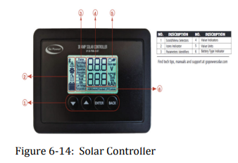
The Go Power 30-Amp Single-Bank Bluetooth-Enabled Solar Controller (Figure 6-14) is designed to regulate the flow of solar energy to your battery system, preventing overcharging and optimizing performance. Here’s how to use it:
1. Powering On & Display: The controller is located at the master control center. Once powered, the backlit LCD screen will display essential battery stats, including battery voltage, PV charging current, and battery state of charge.
2. Bluetooth Connectivity: You can connect the controller to the Go Power! Connect app via Bluetooth. This allows remote monitoring and adjustments, including setting the battery type and toggling Maximum Power Boost mode.
3. Battery Charging Profiles: The controller supports four battery types—Sealed/Gel, AGM, Flooded, and LiFePO4 (lithium). You can select the appropriate profile through the menu settings.
4. Charging Stages: The system operates in four charging stages—Bulk, Absorption, Float, and Equalize—to ensure efficient battery maintenance.
5. Installation & Wiring: The controller features heavy-duty terminals for low-resistance connections and is suitable for 12V solar systems up to 30 amps.
Starlink Mini
The Tiffin GH Series is designed to keep you connected wherever your travels take you, coming standard with Starlink prep for seamless satellite internet integration. This means the vehicle is prewired and ready to support Starlink, ensuring a hassle-free setup for high-speed connectivity on the road. For those who want instant access to satellite internet without additional installation steps, the GH1 also offers an optional Starlink Mini—a compact yet powerful system that delivers reliable internet service in remote locations. Whether you're working remotely, streaming entertainment, or staying in touch with loved ones, the GH Series connectivity options make it easier than ever to enjoy modern conveniences while exploring the open road.
1. Download the Starlink App
Download the Starlink App and scan the QR code to step through the install process.

2. Find A Clear View of Sky and Check for Obstructions
Your Starlink needs a clear view of the sky so it can stay connected with satellites as they move overhead. Objects that obstruct the connection between your Starlink and the satellite, such as a tree branch, pole, or roof, will cause service interruptions. Use the obstruction tool in the app to ensure you have selected a suitable mounting location. Click here for video guidance on obstructions.

If you could not find a clear field of view from the ground level, consider installing in an elevated location, like a roof, pole, or wall. A Mini Pipe Adapter and Flat Mount comes included in the kit and additional mounts and accessories are available for purchase on the Starlink Shop.

3. Plug in Starlink
The Starlink Mini has an integrated Wi-Fi router, meaning a separate router is not required to get online. Lift the kickstand and plug one end of the provided cable into your Starlink. Ensure the plug is fully inserted such that the plug face is flush with the surface. Route the other end of the power cable to your power supply and plug it into a power outlet.

4. Connect to Wi‐Fi
a. On your device, find and connect to the STARLINK network in your Wi-Fi settings
b. To secure your Starlink Wi-Fi network, use the Starlink App to rename your Starlink Wi-Fi network and create a Wi-Fi password.
Open the Starlink App > Settings > Router > enter the desired Wi-Fi network name and password > Save.
- This step is optional, but we recommend securing your Wi-Fi network.

c. You are now connected! Open the Starlink App to customize additional settings, check your connection, and more.
5. Align Starlink
Your Starlink Kit needs to face the right direction to connect to the maximum number of satellites for the strongest connection. Set up Starlink, ensuring the kit is tilted using the kickstand.

Note: If your Starlink is aligned within 5°, the app will not alert you, indicating your Starlink is properly aligned.
Multiple Starlinks: If installing multiple Starlinks in one location, the minimum separation distance from the mount center to mount center should be 3 meters. A third-party router can be used to connect the Starlinks together into one network and provide load balancing, traffic shaping, failover, and other advanced capabilities.
Can't Get Online?
1. Open the Starlink App to check for any alerts, outages, or obstructions.
2. Check the status light on the back of your Starlink.
- Slow Blinking: Powered on.
- No Light: No power to Starlink.
- Fast Blinking: LED will blink quickly for 3 seconds while holding down the reset button, then LED will turn off as your Starlink reboots.
3. Make sure everything is securely and fully plugged in and there is no damage to hardware or cables.
4. Power cycle your Starlink by unplugging from power and then plugging back in.
5. Factory reset the Starlink by locating the reset icon on the back. Press down firmly until you hear or feel a click and hold for 3 seconds. The LED will blink quickly and shutoff when complete. Step through the install process to set up your Mini and get online.
6. Starlink Mini operates with an input voltage range of 12-48V. If you’re experiencing issues while using a 12V power supply or battery, try reducing the cable length or using a thicker gauge cable. You can also improve performance by supplying power at a higher voltage if possible. An easy solution is to use the Starlink Mini USB-C cable with a 100W USB-C power supply or the Starlink Mini Car Adapter.
Note: Your network name and password will be reset after completing factory reset. Look for 'Starlink' network during setup and configure your network to your preferred network name and password.

Using Mesh or Third‐Party Router
If you want to set up a mesh system with a Starlink router, you can hardwire a router via an ethernet cable into the RJ45 port or create a wireless mesh network. You can also use your own router via the RJ45 port in bypass mode. To hardwire a router to your Mini:
1. Remove the Starlink Plug.

2. Plug the Mini Starlink Cable available on starlink.com/shop or your own ethernet cable into the ethernet port. Connect the other end of your cable to a Starlink Gen 3 router or thirdparty hardware.
Note: Use the Mini Starlink Cable available on starlink.com/shop to protect your dish against water ingress. The Mini is no longer IP67 rated waterproof with a third-party RJ45 cable.

3. If you're using a third-party router, use the Starlink App to put the integrated Wi-Fi router into bypass mode. Manual factory reset is required to disable bypass mode.