Girard GG750 Awning: Installation and Service Manual
Access the complete PDF here: Awning Installation and Repair
Warning

ALL ELECTRICAL WORK MUST BE CARRIED OUT BY QUALIFIED PERSONNEL AND CONFORM TO APPLICABLE ELECTRICAL CODES AND STANDARDS.
- Turn off power before beginning any electrical work.
- Please consult your RV’s wiring diagram to locate any wiring prior to any drilling or any installation procedures.
- Ensure that placement of controls, cables, and wires are not in any way obstructed. This can damage the components and obstruct electrical current.
- Use only certified components.

Girard Systems awnings may be operated in light wind and rain conditions. When periods of heavy rain and or high wind are expected the awning must be closed. Never leave the awning open and unattended.
Damage caused by wind and rain is not covered by warranty. All awnings must be closed prior to moving the vehicle for any reason. As an extra safety precaution a visual check that every awning is fully closed is required.
Damage caused by failure to comply with these instructions is not covered by warranty. Before using your awning, ensure that the area into which the awning will be deployed is free of obstructions (Trees, walls, pillars, posts, other vehicles etc.)
Damage caused by collisions with any of the above or similar is not covered by warranty. Before using your awning make sure that all of your electrical circuits are operating correctly.
Basic System Overview
1. Mechanical system – consisting of:
- The enclosure (or cassette) protects the awning while closed.
- The roller tube which is mounted within the cassette.
- The top cover or fabric rolled onto the roller tube and connected to the lead rail that extends from the enclosure when the awning is opened.
- The folding arms that supports the lead rail and the fabric.
- (Option) tubular motor which is mounted inside of the roller tube that controls the extension and retraction of the awning.
- (Option) manual crank handle and drive system that controls the extension and retraction of the awning
2. Electronic controls – (Option) to power and operate the motor
- Motor Control module – 98GC1146C. This works in conjunction with the other electronic controls and the user controls included in the installation to extend and retract the awning as required.
- Motion Sensor – 98GC779, which enables automatic retraction of the awning during periods of high wind that may damage the awning system.
- Wired Motion Sensor – 98GC780B, Wired motion sensor that works in conjunction with 98GC781B and 98GC783B wired wall switch controllers.
3. User Controls – (Option) Hand held remote controllers and wall mounted remote switches will differ according to the individual customer’s needs, single or multi-channel handsets, with or without LED switching facility, and wall switches will differ depending upon how many awnings they are required to control.
- 98GC104 – Single channel awning remote control
- 98GC1063 – Single channel remote with LED switching
- 98GC229 – Single channel remote wall switch
- 98GC781B – Wired wall switch controller
- 98GC783B – Wired wall switch controller
- 98GGC101 – Dual Rocker Switch
Parts
|
Motor Control module |
Motion Sensor
|
|
Wired Motion Sensor Purchase at Tiffin Motorhomes Here |
Wired wall switch controller Purchase at Tiffin Motorhomes Here |
|
Wired wall switch controller |
Single channel awning remote control |
|
Single channel remote with LED switching
|
Single channel remote wall switch |


Installation Manual
FOR PERSONAL SAFETY AND QUALITY OF INSTALLATION, TWO INSTALLERS ARE RECOMMENDED FOR THIS PRODUCT.

Product Description
The GG750 awning system provides protection from the sun at a touch of a button. The GG750 awning is built to your specifications with the highest quality materials available, your unit features:
- A standard 12VDC motor that operates with a wireless motor control or rocker switch.
- Motion sensor that will retract the awning to prevent damage from the wind.
- A hand held remote control
- A wall mounted remote switch
- Options include; electronic automation controls to ensure proper closing at all times, a control to retract all awnings when the vehicles’ motor is started, and more….
The GG750 awning controls use an RF (radio frequency) link to communicate with each other. This simplifies the installation and maintenance by removing the need for extensive wiring. This RF network is called the G-Link system. For more information please refer to the G-Link manual that was included with your awning. All necessary power cables are supplied with this product.
Getting Started
Tools required:
- Electric Drill
- Tape measure
- (2) ladders
- Chalk line
- Flat head screwdriver (small)
- Phillips screwdriver
- Caulking gun
- (2) tubes silicone caulking
- Drill bits: 1/8”, 3/8”, 7/16”, 1/4”
- Allen wrenches: 4mm
- Open-end wrenches: 19mm, 17mm
- Keyhole saw
A. UNPACKING
1. Before starting any of the installation procedures unpack the awning and inspect the product for any possible damage that may have occurred during shipping.
2. Before starting any of the installation procedures ensure that the length, fabric, and motor placement of your awning are correct.
3. When you have determined that the product is to your satisfaction, remove the mounting brackets and place the awning in a safe location while preparing the RV.
a. To remove the brackets locate the slide lock that retains the bracket to the housing. (Figure 1)
b. Using a 4mm Allen wrench, loosen the set screws on the slide locks.
c. Once the set screws have been loosened the slide locks should slide freely, clear the slide lock away from the bracket.
d. You should now be able to remove the bracket.
4. If you have discovered any damage or missing parts please contact your supplier.

B. LAYOUT AND MOUNTING THE BRACKETS
1. AWNING BRACKET APPLICATION – NOTE: Please take into consideration all possible clearances, and obstacles before installing this awning. Items such as slide rooms, etc. vary from one manufacturer to another. Please consult Girard Systems if there are any questions regarding your installation.
a. The mounting brackets can accommodate ¼” lag bolts for mounting.
b. Determine the location for the final installation position of the awning, including height to be installed.
c. Mounting brackets must be installed at the locations shown in bracket placement diagram (see Figure 2a).
NOTE: When installing a three-arm awning, make sure one of the applicable center brackets is directly behind the shoulder of the middle arm.

2. FAILURE TO FOLLOW THESE INSTRUCTIONS WILL VOID THE WARRANTY OF THIS PRODUCT.
a. Now that you have determined the bracket locations, using the bracket as your template, mark the holes for fastening the bracket.
NOTE: Use chalk line to make absolute sure brackets are mounted in straight line.
b. Using a 1/8” bit, pilot drill the centers of the marked holes. Inside of the RV verify the locations of the backing plates.
Note: Please consult your RV's wiring diagram to ensure that no wiring will be damaged while drilling the hole.
c. Pre-drill four 1/4-inch holes per mounting bracket through the pilot holes.
d. Apply a liberal amount of silicone caulking around each hole before installing the brackets.
e. Install the 2 outer brackets, and then the middle bracket(s) (if required) with four ¼ x 1 1/2" carriage bolts, washers, lock nuts and backing plate per bracket. (Figure 2)
f. Tighten bolts and then apply silicone caulking to the top edge and both sides of each bracket.
g. For the motorized option, on the motor side of the awning drill a 7/16 inch hole for the awning motor power cable to enter the RV near the electrical source. Position the hole 4" inch from end of awning. Do not drill hole higher or lower than the bracket. This will ensure that it will not be seen after the awning is installed.
3. SIDEWALL APPLICATION, AWNING RAIL MOUNTING
a. Determine the location for the final installation position of the awning, including height to be installed.
b. Cut the awning rail to 6" less than the awning length.
c. Position the awning rail on the mounting location, making sure it is level.
d. To attach the awning to the awning rail, angle it at 90 degrees and then insert the corresponding track on the awning into the awning rail (Figure 3).
e. Once the awning rail is inserted, rotate the awning down so it is flush with the mounting surface and resting against it.
f. Open the awning to allow access to the inside of the main housing.
g. ON AWNINGS 13' AND UNDER:
- Drill through the back of the awning case (Figure 3) in 3 positions, one in the middle of the awning, and one within 10" or less of each awning aarm shoulders (2 shoulders). Seal holes with applicable sealant and install lag screws and washers to secure the housing to the wall.
h. ON AWNINGS OVER 13'
- If two arm awning, drill through the back of the awning case (Figure 3) in 4 positions, two equally spaced between the awning arm shoulders, and one within 10" or less of each awning arm shoulder (two shoulders). Seal holes with applicable sealant and install lag screws and washers to secure the housing to the wall.
- If three arm awning, drill through the back of the awning case (Figure 3) in 4 positions, one equally spaced between the right hand and left hand arm shoulders and one within 10" or less of each awning arm shoulder (three shoulders). Seal holes with applicable sealant and install lag screws and washers to secure the housing to the wall.
NOTE: All screws supporting the awning assembly must have a minimum .058” aluminum backer or ½” wood backer within the structure of the wall of the unit. Refer to the unit's manufacturer for proper location.
NOTE: Take care not to drill through awning wiring when attaching awning housing to wall.

C. SPRINTER ROOF MOUNT BRACKETS
1. ROOFTOP MOUNT APPLICATION, AWNING BRACKET – NOTE: Please take into consideration all possible clearances, and obstacles before installing this awning. This installation can vary on different applications. Please consult Girard Systems if there are any questions regarding your installation.
a. There are 2 brackets per vehicle shown (see Figures 2a, 2b)
b. Each bracket assembly is recommended to be mounted to vehicle using (6) ¼ inch bolts, three at exterior edge of bracket and three at interior edge of bracket (Figure 2c) It is recommended that sealed rivet nuts are used for attachment of the brackets to the vehicle. When mounting brackets to vehicle use adequate sealant on any attachment holes/hardware.
NOTE: For the interior edge of the bracket it is recommended that at least one attachment point be through the horizontal rib structure of the vehicle for structural reinforcement. NOTE: Pre drilled OEM holes can be used when applicable but the brackets MUST be behind the awning shoulder locations to properly complete installation and for proper function of the awning.
NOTE: Verify the awning does not have slide locks installed as they are not needed for this application.
c. Mount awning to brackets and verify that the awning cassette has properly seated into the brackets.
d. Carefully extend the awning approximately 1-2 feet to gain access to the inside of the case ensuring that the cassette stays attached fully to the brackets. Drill through the awning cassette and bracket on the exterior edge of the awning shoulders and install applicable screws and washers to secure the housing to the brackets.
e. Extend the awning fully. Drill through the awning cassette at the middle and interior edge of the brackets. Add four more screws and washers (two per bracket) to complete awning attachment.


D. MOUNTING THE AWNING.
1. Lift the awning into position for fastening to the vehicle mounted brackets.
a. Ladders are usually sufficient; however, a scaffold or forklift may be used.
b. If using a forklift use all necessary caution to protect the surface of the awning. Lift from the center of the awning to maintain product balance while elevating.
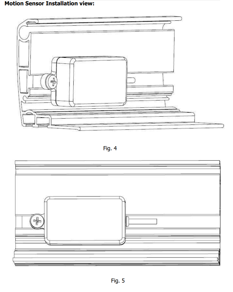
2. Place the awning onto the brackets while feeding the motor power cable through the hole. A small amount of lubricant may aid the feeding of the cable. Make sure the grooves of the awning are securely engaged into the channels on the bracket. (Figure 4)

3. Secure the awning by moving the slide locks along the bottom awning track until they are located under their respective brackets (Figure 5). The final position of the slide lock should be directly under the shoulder of the arm.

4. Once the final location of the slide locks has been achieved, tighten both set screws on each slide lock with a 4mm Allen wrench (Figure 6). This secures the awning in place.

(OPTIONAL, WEATHER STRIPPING NOT INCLUDED, SIDEWALL APPLICATION ONLY)
1. Trim weather stripping to the length of the awning and remove any overhang.
2. Make a small cut in the weather stripping to allow for the motor cord.
3. Apply generous beads of silicone along the weather stripping.
4. Push weather stripping firmly into place.
5. Wipe off excess silicone.
E. ELECTRONIC CONTROLS INSTALLATION
A. Rocker Switch Wiring
The rocker switch is wired according to Figure 8.

B. GC1146C DC Motor Controller Wiring
Wiring Diagram

NOTE: The larger (18) gauge red/black wire coming out of the control box is the incoming power. The smaller (22) gauge red/black wire is the LED outgoing power.
C. Motion Sensor (98GC779G) and LED Connections

Programming the Motion Sensor (98GC779G)
NOTE: All electronic kits shipped from the factory are preprogrammed and do not require programming. This section is intended for reprogramming if required.
1. Remove the 2 small Phillips screws which secure the motion sensor to the awning.

2. Then turn it over.

3. Remove the 4 Phillips screws holding the module together. Remove the base plate and silicone insert.

4. Turn the base plate over (Magnet down). Then place the motion sensor on top of it so that the magnet is aligned with the reed switch.
This is required to allow re-programming

Note; When carrying out this part of the procedure each step must be executed within 6 seconds of the previous one or the module will revert to factory settings. It is highly recommended that you read and understand the following sequence before attempting to execute it.
1. Set the Motion Sensor Adjustment Dial to 0. (See Fig. 4)
2. Connect the GC779G Motion Sensor to a 12 volt DC Circuit.
At this point the Purple LED will illuminate and then begin to blink. If it does not, the unit is not receiving the correct power. Ensure that the magnet and reed switch are aligned and verify the electrical connection before proceeding.
3. Using an appropriate tool, press the P2 Button on the back of the Remote Controller TWICE. The GC1146C will bleep ONCE with each press.
4. Press the programming button on the GC779G Motion Sensor Once (See Fig. 4). The GC1146C will bleep several times to indicate that the program has been accepted.
5. Ensure that the code was accepted by pressing the Program button on the GC779G Motion Sensor again. The Awning should make a small step IN or OUT. Or shake the Motion Sensor and the Awning will fully retract.
6. If the Awning does not retract, repeat steps a. to d.
7. Set the Adjustment Dial to the desired sensitivity level 1-5. Never set higher than 5. (The factory setting is 3).
Once programming is complete, reassemble the Motion Sensor Module and mount it on the Awning lead rail.
D. Switch Control with Wired Motion Sensor

Description
The 98GCK-49 is a combination controller (98GC781” B” or “W”) and Hard Wired Motion Sensor (98GC780” B” or “W”) kit, it can be ordered in either Black or White.
The 98GCK-49 kit is used for a Single DC awning with LED. The 98GCK-49 also includes an Ignition Retract-Lock function to retract the awning if the engine is ON. See wiring diagram to see how to wire this function.
Specification
- Operating Voltage: 11 VDC ~14VDC
- Current: Up to 10A
- LED light control
- RS485 communication to operate the motion sensor
- Maximum run time is 4 minutes
- Operating Temperature 32 to 120F

Mounting Daigram
The required opening to install this Controller is 2 5/8" x 2 5/8" X 1 1/4" depth.


Sensitivity Adjustment:
This unit has 10 levels of sensitivity which can be adjusted directly on the switch.
- Pull off the cover from the switch 98GC781(B), (W).
- Press and hold the set button until you hear a beep from the switch, see Fig. 2 to locate the set button.
- The controller will automatically reset to level 10. Press down to increase the sensitivity level. The LESSER the number the MORE sensitive the sensor.
- The Setting LED will blink a certain number of times with every press to show the level. Recommended factory settings is three. ( That will be three LED blinks when on correct setting).
- Once the level is selected, press and hold the set button again until you hear a beep, then let off the set button. If the programming is successful, you will here three more beeps from the switch to confirm.
Wired Motion Sensor

This wired motion sensor communicates directly to the DC motor Controller 98GC781(B), (W) by RS485 Protocol.
Attach the motion sensor to the lead rail using the mounting tab, see figure 3 above.
E. WIRING DIAGRAM

Testing and Adjustments
Overview
A. Adjusting Motor-limit switches
B. Manual Override
C. Adjusting Pitch and Elbow height
D. Motion Sensor Testing
A. ADJUSTING MOTOR LIMIT SWITCHES
TOOLS REQUIRED
Black plastic key provided with awning, or 4mm (5/32”) Allen wrench.
NOTE: The motor limit switches have been adjusted to the correct positions at the factory prior to shipment. When fully retracted the awning motor is set to stop the exact moment the awning box closes. When fully extended the fabric should be taut and the arms should be slightly bent, exposing a gap of about ¼” at the elbows.
Always check the motor limits after installation to ensure that the awning opens and closes correctly. Awning fabric can stretch over time, this will require an adjustment of the IN and/or OUT limit switch.
IMPORTANT: EXTREME CARE SHOULD BE TAKEN TO ENSURE THAT THE MOTOR LIMIT TURNS OFF AT THE EXACT MOMENT THE AWNING BOX CLOSES. FAILURE TO DO SO WILL CAUSE THE MOTOR TO RUN WHEN THE AWNING IS CLOSED. THIS WILL DESTROY THE MOTOR.
1. The motors used in Girard Systems awnings are reversible.
2. The motor has limit settings for both OUT (extension) and IN (retraction).
3. The limit switches can be adjusted by use of the black key provided with the awning, or you may use a 4mm (5/32”) Allen wrench.
4. Extend the awning a few feet to gain access to the motor. Locate the motor. The limit adjustment screws are located on the head of the motor. Using the symbols printed next to the adjustment screws, turn the black key (or 4mm Allen wrench) to make the necessary adjustments. The motors are labeled with a + or a – to indicate the adjustment direction.

5. Approximately ¼ turn of the adjustment screw represents about 1” of awning movement. NEVER set outward limits so that the fabric is slack with full arm extension. For proper adjustment set limit switch to stop the motor just before the arms lock. This will expose about a 1/4” gap at the elbow.
B. MANUAL OVERRIDE
1. In case of motor issues, the GG750 has a manual override to close the awning.
2. Remove the endcap opposite the motor, by removing the 3 Philips head screws.
3. Using a 13mm wrench, turn the manual override shaft in order to close the awning, see Figure 10. NOTE: The manual override is one-way, it can only close the awning.
4. Figure 10 is showing a right hand motor version of the GG750. If you have a left hand version, the manual override will be on the opposite side.

C. ADJUSTING PITCH AND ELBOW HEIGHT
NOTE: Adjustment of the Elbow height and pitch, will affect the height of the awning lead rail when it is fully deployed.
This adjustment is usually required after an arm replacement. Also, if the elbow of the arm hits the bottom of the casing as the lead rail closes.
Tools Required
17mm open-end wrench
19mm (3/4”) open-end wrench
4mm Allen wrench
1. ELBOW HEIGHT
a. Extend the awning approximately 12”
b. To lower the elbow: Locate screw C located on the side of the shoulder, the top bolt. (Figure 11) Using a 17mm open-end wrench, rotate the bolt counter- clockwise to lower the arm position. Then use a 19mm wrench to tighten Screw D, the bottom bolt.
c. To raise the elbow: Locate screw C located on the side of the shoulder, the top bolt. (Figure 11) Using a 17mm open-end wrench, rotate the bolt clockwise to raise the arm position. Then use a 19mm wrench to loosen Screw D, the bottom bolt.
d. Close the awning completely to ensure smooth operation, that the lead rail lies flush and square along the length of the cassette, and that the arms fold inside the cassette without interference.

2. ADJUSTING PITCH
a. Extend the awning to its fully extended length.
b. Locate screw A, adjustment nut located on front side of the shoulder assembly (Figure 12, 13).
Using a 17mm wrench rotate the nut counterclockwise to lower the pitch or clockwise to raise the pitch. DO NOT OVERTIGHTEN AS THIS WILL RESULT IN DAMAGE TO THE AWNING. LIFTING UP ON THE ARM SLIGHTLY TO RELIEVE PRESSURE MAY BE NECESSARY.
c. Close the awning completely to ensure smooth operation and that the lead rail lies flush and square along the length of the cassette.


D. TESTING THE MOTION SENSOR (Wind Sensor)
1. Partially extend the awning (at least 3 feet).
2. Physically activate the motion sensor by shaking the awning lead rail.
3. At this point the awning should retract; if not, check that there is a 12VDC supply to the motion sensor and that the motion sensor is correctly programmed.
NOTE: The Motion sensor will send a retract signal to the motor of the awning it is programmed to on the RV. If there are multiple awnings extended that begin to retract simultaneously under windy conditions, the power system of the vehicle must be able to withstand the resulting surge of current. The surge will be the greatest when the awnings are fully extended. When testing the system verify all of the awnings will close when fully extended.
E. ADJUSTING THE LEAD RAIL
The lead rail on your awning has been preset at +/- 3 degrees. This allows the lead rail to rest firmly into the cassette and also creates a weather resistant seal for travel. To increase or decrease the pitch angle insert a 4mm Allen wrench into the Pitch adjustment screw, screw B (Figure 13). Turn clockwise to increase the pitch and turn counterclockwise to decrease the pitch. Ensure that the pitch adjustment screw is set evenly on all of the arms.
TROUBLESHOOTING GUIDE
PROBLEM: The lead rail is binding on the side of the awning casing; i.e. the rail is offset from housing.
SOLUTION:
- Open the awning about 3 feet.
- Loosen the lead rail horizontal adjustment screws on all arms (Figure 14).
- Locate and remove the two fabric set screws that are on each end of the lead rail (Figure 14). The lead rail is now ready to be shifted.
- Retract the awning until the lead rail is about 4 inches from the fully closed position.
- Using a rubber mallet, tap the end of the lead rail to move it into the correct position.
- When proper alignment has been achieved tighten the lead rail horizontal adjustment screws (Figure 14), and then replace the fabric screws (Figure 15).


PROBLEM: The motor side of the awning closes when the awning is retracted but the opposite end does not.
SOLUTION: Refer to “Adjusting the Lead Rail” on page 37. If this does not solve the issue please call the Girard Systems service line at (949)259-4000 or toll free at (800)382-8442.
PROBLEM: Motor will not operate.
SOLUTION:
- Check that the panel fuse on the 12VDC circuit is good
- If your vehicle has an Awnings Power Main Switch, locate that switch and make sure it is in the ON position.
- If this does not solve the issue please call the Girard Systems service line at (949)259-4000 or toll free at (800)382-8442.
PROBLEM: The motor will operate for 10-12” and then stop.
SOLUTION: The motor may not be receiving enough power to operate correctly.
- Check to ensure that you have a minimum of 12VDC at the motor connection, if not switch on your generator or connect to shore power.
- If this does not solve the issue please call the Girard Systems service line at (949)259-4000 or toll free at (800)382-8442.
PROBLEM: The fabric is loose when the awning is fully extended; i.e. the roller keeps turning after the awning arms have locked open.
SOLUTION: The motor’s OUT limits must be reset to factory standards. Please refer to the “Adjusting the Motors Limit Switches” section on page 30-31.
PROBLEM: The motor stops before the lead rail has closed completely into the awning cassette on either or both sides. There is no apparent binding of the awning components.
SOLUTION: The GG750 Awning is equipped with a manual override motor which has manual limit settings. The IN limit may need to be adjusted to allow the box to be closed tighter. Refer to the “Adjusting the Motors Limit Switches” section on page 30-31.
PROBLEM: As the awning is closing, the elbow of one or more of the arms is hanging down preventing the case from closing.
SOLUTION: Please refer to the “Adjusting Pitch and Arm (Elbow) Height on page 34-35.
COMMON REPAIR PROCEDURES
MOTOR REPLACEMENT
NOTE: Replacement procedures vary due to motor styles, placement, factory installation methods, and preferences of different vehicle manufacturers. These variations primarily effect how the motors are accessed; replacement operations are generally the same for any situation.
A. REMOVING THE OLD MOTOR
1. Use tie straps on either side of the awning to secure the lead rail of the awning to the cassette. The strap will slide in between the awning and coach wall on each end. Take care to leave slack in the straps so when the motor side endplate is removed the lead rail will open approximately 2" to take pressure off the awning.
2. Identify which side the motor is located on. Proceed to take off the motor side endcap by removing the three #3 Philips screws , there are two located on the bottom and one on top. Please take note that some RV manufacturers have requested the endcap top screw to be left out due to clearance issues with slide toppers.
3. Proceed to take off the motor endplate. (Figure 17) Take caution when taking the last screw out of the plate and when removing the plate as it will be under pressure until it is separated from the motor. Upon removal of the plate the lead rail of the awning will open into the straps freeing the pressure from the motor.
4. Confirm that there is no power heading to motor, cut motor wire close to motor leaving a small amount for warranty testing. Grip motor by the head and pull out of tube making sure to hold the roller tube to keep it in position on other end of awning.

B. INSTALLING THE NEW MOTOR
1. With the new motor in hand, align the notch in the drive (at the far end of the motor) with the indentation in the awning roller tube. Slide the motor all the way in. Turn the motor until its inner notch also lines up with its indentation on the tube.
2. Feed motor cable completely through the hole in the motor plate.
3. Make sure the awning roller tube is still seated and connected into the roller tube support bracket at the opposite end of the awning.
4. Rotate the motor and roller tube assembly until the motor wire is positioned towards the top of the awning.
5. Reinstall the motor plate, lining the square motor peg up with the corresponding slot. Reinstall the 3 screws securing the motor plate (Figure 17).
6. Cut and strip the motor wires preparing for heat shrink butt connection, slide a piece of heat shrink onto one end of the wires.
7. Connect the new motor wires with heat shrink butt connectors and heat shrink.
8. Test for the proper function of the new motor by using the Remote Control or the wall switch. NOTE: The motor limits are not adjusted yet, take care to only test motor to make sure it is moving in each direction a small amount to confirm.
9. After the motor has been replaced, the motors’ limit switches must be adjusted. Please refer to the “ADJUSTING MOTOR LIMIT SWITCHES” section of this manual.
10. Replace motor side awning endcap with applicable screws.
FABRIC REPLACEMENT
A. FABRIC REPLACEMENT PROCEDURE
This procedure involves removal of the awning motor and roller tube to attach the replacement fabric to the existing tube.
NOTE: FOR PERSONAL SAFETY, AND BEST RESULTS IT IS RECOMMENDED THAT TWO TECHNICIANS PERFORM THIS FUNCTION.
B. REMOVING THE OLD FABRIC
1. Partially extend the awning approximately two feet, tie strap each side of lead rail to case to prepare for motor and tube removal. Open awning a few more inches until fabric is slack and pressure is off of fabric/motor.
2. Identify which side the motor is located on. Proceed to take off the motor side endcap by removing the three #3 Philips screws, there are two located on the bottom and one on top. Please take note that some RV manufacturers have requested the endcap top screw to be left out due to clearance issues with slide toppers.
3. Proceed to take off the motor endplate . (#2 Philips, Figure 17) Take note that there will be no pressure on the endplate as long as the fabric is slack and the lead rail is being held by the tie straps.
4. Confirm that there is no power heading to motor, cut motor wire in the middle of wire leaving enough room for reconnection on either side of wire. Leave Motor in end of tube as it will not need to be removed for roller tube removal.
5. Visually identify the white bushing on the non motor side where the roller tube is connected. You will need to make sure upon removal of the tube that this bushing stays installed on the non motor side endplate and doesn't get lost.
6. Take off both lead rail endcaps and remove fabrics screws on either side of lead rail. (Figure 18)
7. The roller tube and fabric are now ready to be removed, take caution and remove tube from housing while sliding the lead rail end of the fabric out of the channel on lead rail, make sure that the motor does not fall out of tube.

C. INSTALLING THE NEW FABRIC
IMPORTANT: REPLACEMENT FABRICS ARE ROLLED AND FOLDED FOR SHIPMENT. THE SEAMS MUST FACE DOWNWARDS AS THE FABRIC IS INSTALLED. THERE IS A SMALL WHITE POLY (POLYESTER) ROPE INSERTED IN THE FABRIC THAT WILL SLIDE INTO THE LEAD RAIL.
1. The old fabric's trim insert will need to be removed from the roller tube, it is held on by clear tape along the length of the tube and black duct tape on each end. Take note of how the trim insert sits in the channel of the tube as the new fabric trim insert will need to be inserted correctly and then taped in the same fashion as the existing insert was attached.
2. With the new fabric attached to the tube, roll up the fabric as even and tight as you can in the correct direction. (The fabric should roll from the bottom of the tube when the awning is extending) Slide the tube with the motor and fabric assembly back into the case of the awning as it came out. Confirm the non motor side of the roller tube is correctly in the bushing that is mounted on the non motor side endplate.
3. Repeat steps 1-10 of motor installation section B.
ARM REPLACEMENT
Follow this procedure when a damaged, spring loaded arm needs to be replaced. There are no repairable parts inside of the arm, if the elbow joint has broken the entire arm must be replaced.
TOOLS REQUIRED:
- 5mm Allen wrench
- 17mm wrench
- 19mm wrench
- Tie down or duct tape

Check arm for wiring: if wired arm, wiring will need to be replaced.
1. Support the lead rail and carefully open the awning a few feet. If the elbow is open tie a large rag around to protect the fabric from the elbow.
2. Remove the 5mm Allen head screw at the lead rail connection, slide out the arm from the lead rail, fold and use a tie down or tape to secure the arm in the folded position very carefully.
3. At the shoulder of the arm (connecting it to the main housing), loosen the 17mm and 19mm bolts on the side (Figure 11).
4. With the shoulder bolts loose, this will allow removal of the arm from the shoulder. Ensure the 17mm and 19mm bolts stay in place on the shoulder.
NOTE: MAKE SURE TO LOOSEN (NOT REMOVE) THE PITCH ADJUSTMENT NUT (FIGURE 13) SO THAT THE ARM ATTACHMENT BOLTS ARE NOT ANGLED WHEN INSERTING NEW ARM
5. Verify the metal sleeve is still on the 19mm bolt inside the shoulder. Attach the new arm to the shoulder using the 17mm and 19mm bolts, tightening both evenly.
6. With the awning open about 18”, unband the high tension arm very carefully. Slowly guide it into position on the lead rail and fasten it in place with the 5mm allen head screw.
7. Adjust the arms’ pitch angle to match the others by rotating the head of the pitch-adjustment screw (Figure 13, screw A) as follows; rotate in a clockwise direction to raise the arm, or rotate counterclockwise to lower it. Fully tighten both lock nuts on the shoulder assembly. Please refer to the “ADJUSTING THE PITCH ANGLE” section of this manual.
8. The elbow height may need to be adjusted, using the 17mm and 19mm bolts (Figure 11).

GG750 COMPONENT IDENTIFICATION

