Starlink: User Guide
Notice
If you are uncomfortable with any part of the installation process, do not attempt — contact a professional to install your Starlink. Starlink is not responsible for injury or damage caused to property due to the installation process.
Please be aware that inclement weather (e.g., heavy rain, snow, or wind) can affect your satellite internet connection, potentially leading to slower speeds or a rare outage.
The Starlink will detect and melt snow that falls directly on it; however, accumulating snow around the Starlink may block the field of view. We recommend installing Starlink in a location that avoids snow build-up and other obstructions from blocking the field of view.
Your mount should be mounted on a horizontal surface, giving your Starlink an 8° tilt. Mounting your Starlink in a vertical position (e.g., on the side of your chimney), will not allow it to operate
Installation Conditions
WARNING! The Starlink router and power supply are rated for both indoor and outdoor use. See Regulatory Notices in your Starlink internet kit for information on environmental specifications of your Starlink and accessories.
Kit Installation for Use on Moving Vehicles Take extra care if installing a Starlink being used on a moving vehicle or vessel. Ensure that the mount is installed on a structurally sound, horizontal surface away from other equipment to give your Starlink a clear view of the sky. Equipment falling on the road or off a vessel due to poor installation practices can cause serious accidents resulting in bodily injury—do not mount the Starlink on any vehicle or vessel if it is not stable, or if it cannot be properly secured as described in this guide.
Starlink may cause interference with other radio transmitting devices Prior to final installation, we recommend turning on the Starlink while using any other radio devices that will be nearby to ensure all devices continue to operate as designed. Install your Starlink at a reasonable distance from these devices if interference occurs.
Safety Notices
WARNING! To reduce the risk of injury, electric shock, or fire, follow basic safety precautions, including:
- Make sure the product’s power is disconnected before accessing, moving, or installing the Starlink (aka “Dishy McFlatface”).
- Plug the power cord into an AC outlet that is easily accessible at all times. If the power cord has a 3-pin attachment, plug the cord into a grounded (earthed) 3-pin outlet.
- Only use the AC adapter and power cord provided with the system or purchased from SpaceX.
- Do not operate this product with a damaged power cord set. If the power cord is damaged, replace before using this product.
- During operation, do not allow the AC adapter to contact skin or a soft surface, such as carpet/rug or clothing. The product and the AC adapter comply with the user-accessible surface temperature limits defined by applicable safety standards.
- Avoid using this product during an electrical storm. There is a remote risk of electric shock from lightning. Do not operate this product if you notice crackling, hissing, popping sounds, a strong odor, or smoke coming from any parts of the system. Turn off the system, disconnect from power source, and contact Starlink technical support for assistance.
WARNING! To avoid injury to persons and damage to property when drilling, take caution and follow basic safety procedures, including:
- Wear appropriate eye, hand, and face protection.
- Avoid studs, electrical wiring, and water lines when drilling. Drilling into any of these can lead to fire, shock, injury, or death.
- Drill at a slight downward angle from the structure interior to the structure exterior and thoroughly apply sealant. Improper drilling and sealing may lead to water and/or bug intrusion and/or damage.
Lightning Protection
If Starlink is used in a lightning-prone area, an external lightning protection system (lightning rod, ground rod, surge protector, etc.) may reduce product susceptibility to lightning. For added protection during a lightning storm, or when it is left unattended and unused for long periods of time, unplug the product from the wall AC outlet and disconnect the antenna cable. This may prevent damage to the product from lightning and power line surges.
The warranty does not cover damage due to:
- Lightning, electrical surges, fires, floods, hail, windstorms, earthquakes, meteors, solar storms, dinosaurs or other forces of Nature.
- Accident, misuse, abuse or alterations.
- Improper or neglected maintenance.
For more safety, regulatory, labeling, and disposal information, refer to the Regulatory Notices in the main internet kit. The information contained herein is subject to change without notice. SpaceX shall not be liable for technical or editorial errors or omissions contained herein.
App Setup
1. Download the Starlink app on your phone.
2. Before installation, use the “Check for Obstructions” tool in the app to identify the best location for uninterrupted service.
3. Setup your Starlink.
4. After connecting, confirm your setup location is obstruction free by reviewing the data coming from your Starlink.
5. Additional app features: customize settings, receive updates, trouble shoot issues, and contact Support.
Plan Your Install
1. Your mount should be installed on a structurally sound, horizontal surface away from other equipment to give your Starlink a clear view of the sky.
NOTE: Don’t allow salt water to collect around your Starlink. Periodically check the sealant on your fasteners and rinse with fresh water.
2. Choose the installation hardware for your mounting surface:
• Option 1: Machine Screws and Nuts — for surfaces with backside access
NOTE: The included machine screws can accommodate mounting surfaces up to 0.3” (11.44 mm) thick. Replacement hardware should be 1/4”-20 (M6) thread, Grade 2, or better. Bolt must protrude through nut 2 threads or more. Use 316 Stainless Steel in marine environments.
• Option 2: Lag Bolts — for wood or plywood
NOTE: Lag Bolts work with a minimum surface thickness of 0.25” (6 mm) thick.
• Option 3: Blind Hole Nuts and Machine Screws — for composite surfaces
NOTE: Blind hole nuts work with surfaces 0.19 – 0.31” (4.5 – 7.85 mm) thick.
3. For use on a vehicle, orient your mount so the low end is pointing forward.

Box Contents
|
Wedge Mount |
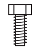
Shoulder Bolts (2) |
Machine Screws (2) 1/2'' in |
Sealing Washer (4) |
Silicone Sealant |
|
Cable Pass Through Kit |
Thread Locker |
Lag Bolts (4) |
Machine Screws (4) 1'' in |
Blind Hole Nuts (4) |
|
Washers (10) |
Lock Nuts (4) |
|||


Additional Items Needed
|
Drill |
Pencil |
Socket Wrench |
3/4'' Spade Bit |
3/32'' Hex Key 1/8'' Hex Key 3/16'' Hex Key |
|
Phillips Head Screwdriver |
3/32'' Drill Bit 1/4'' Drill Bit 1/2'' Drill Bit
|
7/16'' Wrench |
7/16'' Socket |
Box Cutter |


Installation
Option 1- Machine Screws and Nuts
| 1. Using the Wedge Mount as a guide, mark the four corner hole locations with the pencil and remove mount. |  |
| 2. Drill four 1/4” (6.5 mm) holes through the surface at the marked locations. Remove burrs around holes and make sure the surface is free of debris. |  |
| 3. Place rubber sealing washers over holes followed by mount. Liberally apply silicone sealant to fill holes on mount. |  |
| 4. Install a washer on each of four machine screws and apply silicone sealant to threads. Insert the four machine screws to mount and pre-drilled holes. | 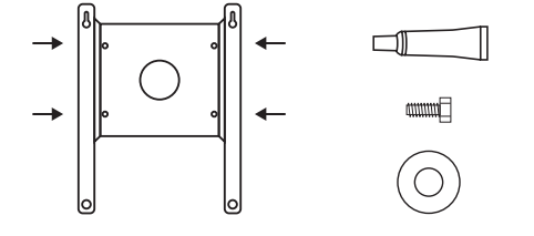 |
| 5. Install a washer and nut on each machine screw and tighten. Use the 7/16” socket and wrench to tighten screws to snug plus 1/4 turn; do not overtighten. | 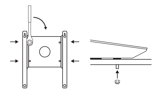 |
Option 2- Lag Bolts
| 1. Using the Wedge Mount as a guide, mark the four corner hole locations with the pencil and remove mount. |  |
| 2. Drill four 3/32” (2 mm) holes through the surface at the marked locations. Remove burrs around holes and make sure the surface is free of debris. | 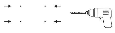 |
| 3. Place rubber sealing washers over holes followed by mount. Liberally apply silicone sealant to fill holes on mount. |  |
| 4. Apply silicone sealant to threads and insert the lag bolts with a washer. Use the drill with 7/16” socket to drive screws ~90% in. |  |
| 5. Use the socket wrench to tighten screws to snug plus 1/4 turn; do not overtighten. |  |
Option 3- Blind Hole Nuts and Machine Screws
|
1. Using the Wedge Mount as a guide, mark the four corner hole locations with the pencil and remove the mount. NOTE: Blind hole nuts work with surfaces 0.18 - 0.31” (4.75 - 7.85 mm) thick. |
 |
| 2. Drill four 1/2” (13 mm) holes through the surface at the marked locations. Remove burrs around holes and make sure the surface is free of debris. |  |
| 3. Apply silicone sealant in and around holes and insert the blind hole nuts. The base of the blind hole nut should be flush with the install surface. |  |
| 4. Install a washer on each of four machine screws and apply silicone sealant to threads. Insert the four machine screws into mount and blind hole nuts. | 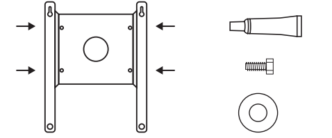 |
| 5. Use the 7/16” socket wrench to tighten screws to snug plus 1/4 turn; do not overtighten. Ensure blind hole nuts are fully collapsed on the interior side of the mounting surface. |  |
Route your Cable
If you want to route your cable through an exterior surface using the provided cable pass through kit, follow the below steps. Otherwise route your cable to the interior and skip to the following section, Install Starlink.
NOTE: The included Starlink cable is 8 m. Different cable lengths can be found on the Starlink Shop at shop.starlink.com.
| 1. Use the 3/4” (19 mm) spade bit to drill a clearance hole to the interior for the Starlink cable. Remove burrs around the hole and make sure the surface is free of debris. |  |
| 2. Wet the drill tube with soapy water and slowly drill a clearance hole in the middle of the rubber plug. |  |
| 3. Using the box cutter, cut the rubber plug from the cable hole to the outer wall. |  |
| 4. Route your cable from the outside through the drilled hole. Place the rubber base gasket around the mounting hole. |  |
| 5. Combine the two halves of the plastic base and mount onto the rubber gasket ensuring alignment with gasket holes. |  |
| 6. Screw down the base with the 4 wood screws. |  |
| 7. Wrap the rubber plug around the cable and press it into the base. Leave 1.5’ (0.5 m) of cable outside. | 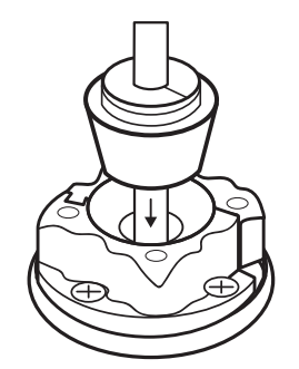 |
| 8. Combine the two halves of the outer shell and seat onto the base ensuring the holes in the inner shell and outer shell are aligned. |  |
| 9. Apply silicone sealant to the four machine screws and hand tighten until snug. |  |
Install Starlink
| 1. Place your Starlink face-down on a clean surface free of debris. Wet shoulder bolt threads with the thread locker and install into threaded holes near the cable port. Use an 1/8” hex key to tighten bolts to hand tight. |  |
| 2. Align shoulder bolts into the keyway on the bottom of the mount. Push down and slide Starlink forward to lock into place. |  |
|
3. Wet threads of the 1/2” long machine screws with thread locker and install into the two remaining holes with two washers to secure Starlink. Use the 3/16” hex key to tighten screws to snug plus 1/4 turn; do not overtighten. NOTE: Ensure you are using the 1/2” length screws. Longer bolts can damage Starlink. |
 |
|
4. Plug the Starlink cable into the port on the bottom of the Starlink. NOTE: Do not make sharp turns with your cable, use a minimum bend radius of 2” (50 mm). |
 |