Truma AquaGo Comfort Operating Instructions
Operating Instructions
How the appliance works
The appliance was developed exclusively for use in recreational vehicles (RVs). The appliance is connected between the vehicle’s fresh water supply and its hot water plumbing system. It is powered by propane and a 12 V power supply. The ventilation grille on the access door allows combustion air to flow into the appliance and exhaust gas to flow out. When the appliance is switched on, the water will be heated on demand:
- A volume-flow sensor in the appliance detects when the hot water faucet has been opened and the volume flow is greater than approximately 0.4 gallons/min (1.5 liter/min). The burner then starts automatically.
- The burner control continously adjusts the heater output based on volume flow and inlet water temperature, so that the temperature at the hot water outlet is approximately 120 °F (49 °C). A temperature stabilizer is also installed in the appliance to minimize fluctuations of the outlet temperature.
- After some time the maximum temperature at the faucet or in the shower is reached. The length of time will depend on the model (AquaGo basic, AquaGo comfort and AquaGo comfort plus) and variations in the water plumbing (length of pipes, insulation, circulation line, etc.). Like in a home shower, a comfortable water temperature at the shower head is reached by mixing in cold water.
- When the volume flow is less than approximately 0.4 gallons/min (1.5 liter/min) and the faucet is closed, the burner is automatically switched off.
The AquaGo comfort and AquaGo comfort plus models are equipped with a circulation pump. The circulation pump as well as the burner are switched on automatically by the control unit in order to keep the water temperature above 102 °F (39 °C) in “COMFORT” mode and 41 °F (5 °C) in “ECO” mode.
Pressure relief valve
- The pressure relief valve is a safety component and must not be removed for any reason other than replacement.
- The pressure relief valve is not serviceable; if defective, it must be replaced.
- It must be replaced by a Truma pressure relief valve rated for 100 psi (6.9 bar) that is CSA-certified and registered.
- It must be replaced by a Truma certified service technician.
- Tampering with the pressure relief valve will void the warranty.
The appliance is equipped with a pressure relief valve (Fig. 3) that complies with the standard for Relief Valves for Hot Water Supply Systems, ANSI Z21.22
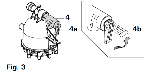
| 4 | Pressure relief valve |
| 4a | Lever in “valve closed during operation” position |
| 4b | Lever in “open” position |
Access door
Opening the access door
- Turn the turn lock counterclockwise into the vertical position.

- The access door can be opened in two different positions:
- Position 1 is the maximum opening width for switching the appliance on or off.
- Position 2 is the starting position for removing the access door.
- Open the access door to Position 2.

Removing the access door
- Open the access door to Position 2.
- Move the access door upwards to remove it.

Closing the access door
- If removed, insert the access door into the cover plate.
- Make sure that the webbing is not pinched between the access door and the cover plate.
- Press the access door against the cover plate.
- Turn the turn lock clockwise into the horizontal position.

Starting the appliance
Inspections before each use
Check the appliance for the following points before each use. In case of damage, contact an authorized Truma service provider and do not operate the appliance.
- Check for visible damage, e.g., on the cover plate or access door.
- Provide adequate quantities of propane gas and fresh water.
- Switch ON and check 12 V power supply of your RV.
- Check that the access door of the appliance is closed.
- Keep the appliance free of foreign objects, e.g., leaves, animals, spiderwebs, and keep the area around free of snow and ice. The appliance will not function properly if the intake air or exhaust terminal is obstructed.
Operating procedures
Proceed as follows to fill the appliance with water:
- Close open bypass lines (if present). Insert the water inlet filter or heating cartridge – if removed. 2, 7, 9 – 11.
- Turn on fresh water supply or switch on water pump.
- Fill the plumbing system.
- Open all water-release points, e.g., cold and hot water faucets, showers, toilets.
- It is important that you bleed the water system before starting the appliance.
- Once water flows, the plumbing system is vented. Close the water-release points.
- Start the appliance as follows:
- Make sure that the LP gas supply is turned on.
- Switch on the 12 V power supply (RV).
- Open the access door (refer to “Opening the access door”).
- Switch on the appliance at the POWER switch. Refer to “Switching ON the appliance”.
- AquaGo comfort/AquaGo comfort plus:
- Select the desired operating mode (refer to “Operating modes (control panel)”
- Close the access door (refer to “Opening the access door”).
- There may be a variation between the temperature delivered from the appliance and the temperature at the faucet due to water conditions or the length of pipe from the appliance.
- The presence of a flow restrictor in the hot water line may limit the water flow.
How to use hot water:
- To obtain the desired water temperature at the faucet or in the shower, mix cold and hot water.
- Particularly when showering, wait until the water temperature has stabilized before entering or allowing other people or animals to enter the shower.
Switching ON the appliance
- Open the access door (refer to “Opening the access door”).
- To switch on the appliance, switch the POWER switch (Fig. 8 – 8) to one of the two “ON” positions. Both ON positions on the POWER switch have the same function. Choose your preferred position.
- When the green power ON LED 1 (Fig. 8 – LED 1) is lit, the appliance is switched on.
- If the red error code LED 2 (Fig. 8 – LED 2) is lit/flashes, there is a fault or warning (refer to “APPENDIX A – Error Codes”).

AquaGo basic
- The operating mode is set automatically to “BASIC”.
- The appliance is now ready for use.
- Water temperature at the outlet is approximately 120 °F (49 °C).
AquaGo comfort/AquaGo comfort plus
- The appliance is now ready for using the control panel inside your vehicle. Refer to “Operating modes (control panel)”.
Operating modes (control panel)
AquaGo comfort/AquaGo comfort plus: A control panel to select the operating mode (included with the delivery from serial number DLE60X(X)27100000).

With the rotary switch (Fig. 9) you can choose between the following operating modes:
| Sign | Operating mode / Description |
 |
ECO |
|
The appliance is now running in energysaving mode.
|
|
 |
COMFORT |
|
The appliance is now running in a mode that provides rapid availability of hot water.
|
|
 |
Stand-by. The appliance is not running in any operating mode.
|
 |
ANTIFREEZE |
|
Prevention of freezing using 12 VDC electricity:
|
|
 |
DECALCIFICATION |
|
| Description of the yellow status LED 3 |
| Signal | Meaning |
| LED 3 lit | Appliance is switched ON |
| LED 3 is off | Appliance is switched OFF. Refer to “Switching OFF the appliance” |
| Every 7 seconds, LED 3 is interrupted for 1 second | The appliance must be decalcified |
| LED 3 flashes slowly 1 second on, 1 second off | Decalcification mode has been activated |
| LED 3 flashes quickly | Before you use the water system you must rinse it (refer to step f) “Rinsing the water system” |
| LED 3 flashes 2 times briefly after a break | There is a fault in the appliance. The exact fault diagnosis must be determined via error LED 2. Refer to “APPENDIX A – Error Codes”. Risk of freezing if the temperature in the appliance is below 37.4 °F (3 °C). |
Operation in frost conditions
(Ambient temperatures below 39 °F (4 °C))
Only AquaGo basic
- Never operate the AquaGo basic in frost conditions, this model must be winterized (refer to “Winterizing”).
Only AquaGo comfort/AquaGo comfort plus
When the vehicle is standing, to -4 °F (-20 °C)
- The appliance has a built-in thermostat that will start the burner and the circulation pump whenever the temperature in the appliance falls below 41 °F (+5 °C). The burner will automatically shut off when it senses a temperature above 111 °F (44 °C).
- For the appliance to operate properly, you must ensure a constant supply of power (12 V), propane gas, sufficient water in the system. You must leave the appliance powered “ON”. The operating mode must be “ECO” or “COMFORT”. The water system must be bled so that the circulation pump works.
- If the vehicle is standing and ambient temperatures are below -4 °F (-20 °C), the appliance must not be operated and must be winterized. To winterize the appliance refer to “Winterizing”.
While driving (or if there is no gas supply), to -4 °F (-20 °C)
- Gas must not be used for heating while the vehicle is in motion. Ask your dealer/vehicle manufacturer about options for heating your RV while driving.
- An electric antifreeze kit is available as an accessory (ask your dealer). With this kit, the appliance can be kept frost-free while you are driving or if there is no gas supply (to ambient temperatures of -4 °F (-20 °C)). The electric antifreeze kit includes detailed instructions.
- While the vehicle is in motion and at ambient temperatures below -4 °F (-20 °C) the appliance must not be operated and must be winterized. To winterize the appliance refer to “Winterizing”.
Winterizing
If your RV is equipped with a bypass around the appliance, separate the appliance from the water system with the bypass.
Winterizing the appliance
To winterize the appliance, you must drain all water from the appliance. To do this we advise the following steps:
- Remove the water inlet filter or heating cartridge. See “Draining the water and cleaning the water inlet filter", steps 1 to 8.
- Let water completely drain from the appliance. This can take several minutes.
- Do not insert the water inlet filter or heating cartridge into the appliance during winter – if the appliance is not used.
- Danger of crushing/pinching of fingers when the Easy Drain Lever is closed! Never put fingers between the Easy Drain Lever and latch.
- Close the Easy Drain Lever and the access door.
Once the water has been drained, the appliance is protected against freezing conditions.
Winterizing the RV with a winterizing fluid
- Winterizing the RV with a winterizing fluid is only possible with an installed bypass kit (not in scope of delivery)
- Refer to “Connection diagrams” for all letters referred to in the following description.
Winterizing AquaGo basic/AquaGo comfort
- Close valves A and B.
- Open valve C.
- Drain the appliance (“Draining the water and cleaning the water inlet filter”).
- Flush the RV’s water system with a suitable winterizing fluid according to the supplier’s or RV manufacturer’s guidelines.
Winterizing AquaGo comfort plus
- Close valves A, B and E.
- Make sure that valve D remains in the closed position.
- Open valve C.
- Drain the appliance (“Draining the water and cleaning the water inlet filter”).
- Flush the RV’s water system with a suitable winterizing fluid according to the supplier’s or RV manufacturer’s guidelines.
- Close all faucets (if open).
- Open valve D.
- Wait until winterizing fluid has drained. Collect escaping fluid in a suitable vessel.
- Close valve D.
| AquaGo technical data |
| BTU/h (Nominal input rate) | 20,000 – 60,000 |
| Fuel | LP gas (propane only) |
| Fuel inlet pressure | 10.5 – 14 in. wc (26.2 – 34.9 mbar) |
| Fuel manifold pressure | 1.3 – 10 in wc (3.2 – 24.9 mbar) |
| Nominal voltage | 12 V DC (< 1 Vpp) |
| Power input | |
| AquaGo basic | < 1.5 A |
| AquaGo comfort | < 2.5 A |
| AquaGo comfort plus | < 2.5 A |
| Water operating pressure | 65 psi (4.5 bar) max. |
| Standard water outlet temperature | 120 °F (49 °C) |
| Water volume | 0.35 gallons (1.3 liter) |
| Ambient temperature | |
| AquaGo basic | +32 °F…+104 °F (+5 °C…+40 °C) |
| AquaGo comfort AquaGo comfort plus | -4 °F…+104 °F (-20 °C…+40 °C) |
| Dimensions (without flange and frame) | |||
| Width | Height | Depth | |
| in. | 12.5 | 12.5 | 15.5 |
| mm | 318 | 318 | 394 |
| Dimensions of frame | |||
| Size XS | |||
| in. | 15.1 | 15.5 | 0.8 |
| mm | 384 | 394 | 20.2 |
| Standard | |||
| in. | 17.7 | 17.7 | 0.8 |
| mm | 450 | 450 | 20.2 |
| Adapter | |||
| in. | 20.1 | 20.1 | 0.8 |
| mm | 510 | 510 | 20.2 |
| Installation cutout and depth | |||
| Width | Height | Depth | |
| in. | 12.8 | 12.8 | 17.7>19.7 |
| mm | 324 | 324 | 450>500 |
| Weight of unit without access door | (approx.) 34.2 lbs (15.5 kg) | ||
| Weight of access door standard and access door XS | (approx.) 2.9 lbs (1.3 kg) | ||
| Weight of access door adapter kit | (approx.) 5.5 lbs (2.5 kg) | ||
Maintenance
Repairs must be performed by a certified service technician. Truma recommends that the appliance be serviced annually by a certified service technician. Verify proper operation after servicing.
Draining the water and cleaning the water inlet filter
To keep the appliance fully functional, clean the water inlet filter at least once a year.
- AquaGo comfort/AquaGo comfort plus Set the control panel to “Off”.
- Remove the access door (refer to “Removing the access door”).
- Switch OFF the appliance at the POWER switch.
- Open all hot water faucets and wait for cold water. This will ensure that hot water is removed from the appliance before draining.
- Turn OFF the water supply or switch OFF the water pump.
- Leave the hot water faucets open in order to depressurize and vent the water system.
- Open the latch with your thumb while pulling the Easy Drain Lever down as far as it will go.
- Remove the water inlet filter (or heating cartridge) as shown in Fig. 10 and rinse it with clean water.
- Inspect the O-rings on the water inlet filter (or heating cartridge) for cracks. Change the filter assembly (spare part, refer to “APPENDIX C – Spare Parts (all models)” ) if there are cracks.
- If, during installation, it is difficult to install the filter cartridge, use a small amount of soap on the O-rings. Never use grease because the O-rings are not resistant to grease.
- Install the water inlet filter as shown in Fig. 10. Observe the correct installation position and close the Easy Drain Lever until it is locked by the latch. You can hear a “clicking” sound as the Easy Drain Lever engages.
- Insert and close the access door (refer to “Closing the access door”).

Decalcification
Decalcification frequency
Lime scale occurs especially as a result of precipitation from “hard” water. The appliance must be decalcified regularly depending on water hardness and hot water consumption.
| Recommended decalcification frequency per year | |||
| Use | Low | Normal | High |
| Very hard >180 | 1 | 2 | 4 |
| Hard 121 – 180 | 1 | 1 | 3 |
| Moderately hard 61 – 120 | 1 | 1 | 2 |
| Soft 0 – 60 | 1 | 1 | 1 |
Decalcification (models with control panel)
AquaGo comfort/AquaGo comfort plus with control panel (included with delivery).
An integrated water consumption meter recognizes (after hot water consumption of approx. 1585 gallons / 6000 l) that decalcification is necessary. The assumed water hardness is “hard” and cannot be changed. The yellow status LED 3 (Fig. 9) indicates that decalcification is necessary (goes off briefly about every 7 seconds).
During decalcification, you must also observe the following
- Damage to the appliance if decalcification is interrupted.
- You must complete the decalcification process and then rinse thoroughly with clean water.
- Allow about 3 hours for decalcification. The appliance works on its own for most of this time.
- Sensitive surfaces (e. g. marble) may be damaged through contact with the decalcification agent.
- Immediately remove splashes of decalcification agent on these surfaces.
- Preparing for decalcification
- For safety reasons, once the decalcification process has started it must not be stopped until the system has been rinsed (see process f). All operating modes of the appliance are blocked until decalcification has been completed.
| Tasks within the RV |
| Set the control panel to “Off”. |
| Turn OFF the water supply or switch OFF the water pump. |
| Open a hot water faucet to relieve pressure in the system. |
| On all water faucets attach the warning sign “Caution decalcification in progress” in a clearly visible position. Warning signs are enclosed with the decalcification tablets. |
- Draining the water system
| Tasks outside the RV |
| Remove the access door (refer to “Removing the access door”) |
| Switch OFF the appliance at the POWER switch. |
| Drain the water system and remove the water inlet filter. To do this, refer to “Draining the water and cleaning the water inlet filter”, Steps 4 to 8. |
| You must use the water inlet filter for decalcification (included with the delivery Fig. 1 – 11a). If you are using an electric antifreeze kit, it must be removed and be unplugged from the power supply before decalcification (see Fig. 11). |
 |
- Introducing the decalcification agent
| Tasks outside the RV |
| Irritation of skin and eyes in case of contact with decalcification agent. Wear protective gloves, eye protection and face protection to avoid contact |
| Fill the water inlet filter with 6 AquaGo decalcification tablets (content of one blister pack). |
 |
| Re-insert the water inlet filter. See Step 9 in “Draining the water and cleaning the water inlet filter”. |
| Switch ON the appliance at the POWER switch. |
- Filling the water system
| Tasks within the RV |
| Turn on fresh water supply or switch on water pump |
| The decalcification tablets dissolve in water quickly (approx. 10 minutes). So that the decalcification agent is not rinsed out, when filling, run the water only as long as necessary. The decalcification tablets color the water slightly red. |
|
Fill the water system.
|
- Starting decalcification
| Tasks within the RV |
|
Set the control panel to “Clean”.
|
- Decalcification takes about 3 hours (during this time, you do not have to do anything).
- Decalcification is indicated by a slow flashing (1 s on, 1 s off) of the status LED 3 (Fig. 9) on the control panel.
- During decalcification, the control panel must remain set to “Clean”.
- Decalcification is complete when the status LED 3 (Fig. 9) flashes quickly on the control panel.
- Rinsing the water system
- You will need about 8 gallons (30 liters) of water to rinse the water system.
- Dispose of (used) decalcification solution in accordance with local laws and regulations.
| Tasks within the RV |
| Open all water-release points, e.g., hot water faucets, showers, toilets. |
| Run the water until the status LED 3 (Fig. 9) on the control panel goes out. |
| Set the control panel to “Off”. |
| Close all water-release points. |
| Turn OFF the water supply or switch OFF the water pump. |
| Open a hot water faucet to relieve pressure in the system. |
| To make sure that the appliance and the water pipes contain no decalcification agent, empty the water system again and refill it. |
| Tasks outside the RV |
| Switch the appliance OFF at the POWER switch (red error code LED 2 (Fig 8) flashes before it switches off). |
| Drain the water system (refer to “Draining the water and cleaning the water inlet filter” on page 15, steps 4. to 8.). |
|
Install the water inlet filter* referring to step 9. * or antifreeze cartridge if electric antifreeze kit is installed. |
| Switch ON the appliance at the POWER switch. |
| Insert and close the access door (refer to “Closing the access door”). |
- Filling the water system
| Tasks within the RV |
| Turn on fresh water supply or switch on water pump. |
|
Fill the water system.
|
|
Before you use the water system and the appliance, check the color of the water at all faucets:
|
| Remove the warning signs “Caution decalcification in progress |
Interrupting decalcification
- Decalcification can be interrupted by switching the control panel to “Off”.
- Decalcification is interrupted after about 2 s.
- The status LED 3 (Fig. 9) on the control panel flashes quickly.
- Irritation of skin and eyes in case of contact with decalcification agent. Wear protective gloves, eye protection and face protection to avoid contact.
- First you must take out the water inlet filter and remove any AquaGo decalcification tablets that it may contain.
- To take out the water inlet filter, see “Draining the water and cleaning the water inlet filter”.
- Dispose of AquaGo decalcification tablets in accordance with local laws and regulations.
- Before you use the water system again, you must rinse it (see step f) “Rinsing the water system”) and fill it with water (see step g) “Filling the water system”).
Troubleshooting |
||
| Problem | Potential Cause | Resolution |
| No hot water at the faucet | Gas supply is turned off or interrupted. | Check and/or turn on gas supply. |
| Gas tank is empty. | Refill/replace the gas tank. | |
| The appliance is switched off. | Switch on the appliance according to instructions (refer to “Operating procedures”). | |
| Fresh water supply is turned off. | Open the fresh water supply | |
| Power supply to the appliance is switched off. | Switch on power supply to the appliance. | |
| Defect in the appliance. | LED 2 flashes red (refer to “APPENDIX A – Error Codes”) and contact a certified service technician if necessary. | |
| Boiling noises | Too much lime scale in the AquaGo instant water heater. | The appliance must be decalcified (refer to “Decalcification”). |
| Hot water temperature too low. | Gas flow to the appliance is too low (gas inlet pressure < 10.5 in. wc). | Consult vehicle documentation to determine if the gas supply is capable of providing the necessary volume of gas for the appliance. Contact a service technician to verify that the gas installation is suitable. |
| Volume flow of hot water is too high and/or the temperature of cold water reaching the appliance is too low | Turn down hot water at the faucet or in the shower in order to reduce flow rate. Potentially retrofit a flow rate throttle in the water system. This must be performed by a certified service technician. | |
| Too much lime scale in the appliance | The appliance must be decalcified (refer to “Decalcification”). | |
| Water escaping at pressure relief valve. | Water pressure in water system too high. | Adjust the water pump pressure to a maximum of 65 psi (4.5 bar). If the water system is connected to a central water supply higher than 65 psi (4.5 bar) (rural or urban connection), a pressure reducer must be used. Install a pressure reducer (e.g. Truma pressure reducer) at the fresh water supply. |
| Water cannot expand in the water system. | Contact the vehicle manufacturer about retrofitting a pressure compensation element. | |
| Lime or dirt under the pressure relief valve seat. | Allow the appliance to cool and then slowly raise the test lever (Fig. 3 – 4a) to flush the water system and attempt to force dirt or foreign matter out of the pressure relief valve seat. Replace pressure relief valve. This must be performed by a Truma certified service technician. | |
| Water escaping at water inlet filter | Lime or dirt under the O-ring seats. | Clean the O-rings and their corresponding sealing surfaces with clean water. |
| AquaGo comfort / AquaGo comfort plus | ||
| The yellow status LED 3 is off although an operating mode was selected. | Power switch is OFF. | Switch ON the appliance at the POWER switch. |
| Power supply to the appliance is switched off. | Switch on the power supply to the appliance. | |
| Power supply was interrupted. | Reset by switching OFF at the control panel, waiting 2 seconds and then switching on again. | |