07 Instruments & Controls
GRAPHICAL INSTRUMENT CLUSTER
OPERATION MANUAL
VDC00249 TIFFIN, 12.3" DISPLAY
Saftety Instructions
WARNING
▶ Driving while distracted can result in loss of vehicle control.
▶ Do not make adjustments in the selectable display on the graphical instrument cluster under conditions that will affect your safety or the safety of others.
CAUTION Your graphical instrument cluster system should be serviced only by qualified personnel.
Overview
The Graphical Instrument Cluster (GIC) is primarily a display device that communicates electronically with multiple pieces of equipment on the coach.
To familiarize yourself with the indicators and gauges, refer to the quick reference guide on pages 6 and 7.
The display will automatically dim for nighttime driving when the headlights are activated.
A selectable display within the tachometer gauge provides a menu system which is navigated by rotating and pressing a joystick knob. Refer to page 26 for the menu selections:
• Speedometer
• Display brightness
• Pre-drive item reminders
• Selectable gauges
• Tire pressure and temperature for coach & trailer
• Trip 1 and Trip 2
With the coach stopped and the park brake applied, the menu also provides the following items:
• Choice of towable trailer/vehicle for the tire pressure monitoring system (TPMS).
• Sound volume for alerts.
• Measurement units for speed/distance, temperature and pressure.
• Background image and brightness.
• Gauge needle color.
• Vertical position of screen display. • Diagnostics for system, onboard diagnostics (OBD) and controller area network (CAN-Bus).
Cleaning your GIC screen
The glass on the GIC screen is treated with an optical coating to prevent glare and reflection. It should be cleaned with a product that is designed for this, such as the optical wipes included with the screen, or optical cleaner and a microfiber cloth.
WARNING: The screen surface can be damaged if not treated with care.


Navigation
Joystick Knob
The joystick knob is connected directly to the GIC and is primarily used to navigate the selectable display by rotating the knob to scroll the menu or view and pressing to select that item (refer to page 17).
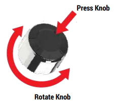
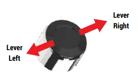
In addition to being pressed or rotated, the top can be levered sideways to the left or right. Do this to toggle between the selectable displays for the speedometer and tachometer.


Gauges
Engine Coolant Temperature
This gauge measures the temperature of the engine coolant fluid. The message center will display a warning and sound an alert when the temperature is higher than the red warning level.
Engine Oil Pressure
This gauge measures the pressure of the engine oil, which is required to ensure efficient lubrication of the internal engine parts. The oil pressure will increase as the engine RPM is increased from idle to normal driving speed. An oil pressure warning is an indication to seek service at the earliest opportunity.

The message center will display a warning and sound an alert when the pressure is less than the red warning level.
Speedometer
The speedometer displays the speed of the vehicle in miles or kilometers per hour, both with a needle and as a digital readout.
Also found on the speedometer is the fuel gauge, generator gauge, cruise control indicator, and current gear.
With the coach stopped and the park brake applied, you can change the display units between miles and kilometers with the Selectable Display selection Settings > Units > Speed / Dist.
The color of the gauge needle can be configured in Settings > Needle Color.

Cruise Control
The Cruise Control indicator is gray when the feature is enabled. It is green when the feature is active and a fixed vehicle speed has been set by the operator.
Odometer
The odometer displays the lifetime mileage of the vehicle from when it was manufactured.
Fuel Level – Engine & Generator
The fuel level is displayed at the bottom of the speedometer. When fuel falls below the factory programmed low level, the fuel indicator will turn red and an alert will sound. The generator gauge is a static gauge that indicates the point at which the generator will run out of fuel.
The GIC is connected directly to the fuel tank level sender. Provided the chassis battery level is greater than the factory-configured ‘Power Off’ level, it continues to send fuel level messages over the RV-C network with the ignition off. This allows the fuel level to be viewed on the Coach Management System for operation of the coach generator.
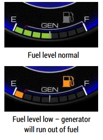
Note that the generator will run out of fuel before the engine does. As indicated on the gauge, the generator will stop running while there is still an eighth of a tank of fuel left. This provides the operator with the opportunity to drive to a fuelling station.
Message Center
The message center is between the speedometer and the tachometer. During normal operation, this area displays the vehicle logo. When necessary, the message area shows three categories of alarms:
 INFORMATION: These relate to normal operation of the coach. Refer to page 21.
 CAUTION: These indicate items which require your attention. Refer to page 22. A chime may also sound when an alarm occurs.
 CRITICAL: These indicate items which require your immediate attention. Refer to page 25. A chime may also sound when an alarm occurs. When an alarm occurs it is immediately displayed. After a short delay, the display will then continue to cycle through each active alarm.
Trip Meter/Fuel Economy
Trip 1 or Trip 2 are items in the Selectable Display. Rotate the knob to display the item. Press the knob to switch between Trip 1 and Trip 2. Hold the knob to reset. Refer to the menu map on page 26.
The odometer displays the lifetime mileage of the vehicle from when it was manufactured.

The average fuel economy and distance to empty can be configured in miles or kilometers. This changes the display between miles per gallon / miles and liters per 100 kilometers / kilometers. Refer to the menu map: Settings > Units > Speed / Dist.
Tachometer
The gauge displays engine revolutions per minute (RPM).
The color of the gauge needle can be configured in Settings > Needle Color.

Diesel Exhaust Fluid (DEF) Level
The diesel exhaust fluid (DEF) level is displayed on the lower left of the tachometer. When the DEF level falls below the factory-programmed low level, the DEF indicator will turn amber and an alert will sound.

The low Diesel Exhaust Fluid (DEF) indicator is illuminated by a message from the engine controller. It has four low level thresholds which determine if the DEF indicator is solid or flashing. Refer to the description on page 12.
Chassis Battery Voltage
This gauge measures the chassis batteries, which are used when driving the coach; for example, starting the engine.

When the voltage falls below 11.5V, the battery indicator will turn red and an alert will sound.
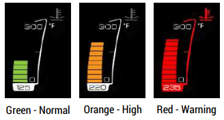
Front and Rear Air Tank Pressure
The bar gauge color on the front and rear air pressure gauges indicates the following levels:
• Green is normal.
• Orange is slightly low.
• Red is critically low. A warning sound will also occur.

The front air pressure gauge is shown; however, the levels are the same for the rear air pressure gauge.
Compass
The compass displays the direction in which the vehicle is heading.

Outside Temperature
The outside temperature is displayed according to data collected by either RVC (Spyder) or the engine ECU. Units can be changed from Fahrenheit to Celsius in the Settings menu (see page 27).

Time
The time is displayed in the selectable display area of the tachometer.

Selectable Display
The center of the tachometer can display a variety of information as desired by the user. This information can be selected with the use of the joystick knob. Rotate the knob clockwise and counter-clockwise to scroll up and down the menu items. Press the top button to select that menu item.

The following information is available:
• Trip information (Trip 1, Trip 2, fuel economy)
• TPMS (Tire Pressure Monitoring System)
• TPMS Trailer (if enabled)
• Information Gauges
• Pre-Drive List
• Brightness
• Settings
Refer to the menu maps on pages 26 & 28 for all available menu options.
Trip 1, Trip 2 and Fuel Economy
The fuel economy is calculated by the engine controller. ‘Inst. Economy’ is the instantanteous fuel economy of the vehicle. For example, when driving uphill, a higher value will be displayed than when driving downhill.
Note: Refer to page 15 for information on the the average fuel economy display.
With the coach stopped and the park brake applied, you can also change the display units between miles and kilometers with the Selectable Display selection Settings > Units > Speed / Dist.

Note: With miles selected, fuel information displayed in US gallons and miles per gallon. With kilometers selected, fuel information is displayed in liters and in liters per 100 kilometers.
TPMS (Coach Tire Pressure)

Selectable Display
Tire Pressure (Coach) is an item in the Selectable Display. Rotate the knob to display the item. Press the button to toggle between tire pressure and tire temperature. With the park brake set, press the button for 5 seconds to display the Tire Pressure Monitor (TPMS) screen. Refer to the menu map on page 26. Note that the bracketed items pertain to the coach tire pressure.
The status of each tire is represented by a color:
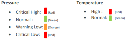
The thresholds for pressure and temperature are set at the factory. However, the pressure thresholds are around the ‘normal’ pressure which is established when the pressure sensor is screwed onto the tire valve.
TPMS Trailer (Trailer Tire Pressure)

Tire Pressure (Trailer) is an item in the Selectable Display. Rotate the knob to display the item. Press the button to toggle between tire pressure and tire temperature. With the park brake set, press the button for 5 seconds to display the Tire Pressure Monitor (TPMS) screen. Refer to the menu map on page 26.
Note that the bracketed items pertain to the trailer tire pressure.
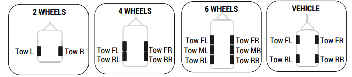
This example shows a 2 wheel configuration.
The status of each tire is represented by a color:
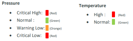
The thresholds for pressure and temperature are set at the factory. However, the pressure thresholds are around the ‘normal’ pressure which is established when the pressure sensor is screwed onto the tire valve.
Selectable Display
Information Gauges
Information gauges do not have any warning threshold levels. You may choose to display a single gauge, or select the item to continuously scan through each gauge every five seconds. Scan mode is indicated by the symbol 

Pre-Drive
Pre-Drive is an item in the Selectable Display. Use the knob rotation and button press to choose this. Refer to the menu map on page 26.
This is an auto-scrolling list which displays active items requiring attention prior to vehicle travel.
After viewing, rotate the knob to select another menu item.

Brightness
The display Brightness is an item in the Selectable Display. Use the knob rotation and button press to choose this. Refer to the menu map on page 26.
Different brightness levels can be set for daytime or nighttime driving. If the headlights are off when the brightness is adjusted, the brightness level will be saved for driving with the headlights off (daytime). If the headlights are on when the brightness is adjusted, that level will be saved for driving with the headlights on (nighttime).

Rotate the knob to adjust the brightness and then press the knob to save for that mode and return to the previous menu.
Settings
The coach must be stopped with the park brake set for this menu item to be available.
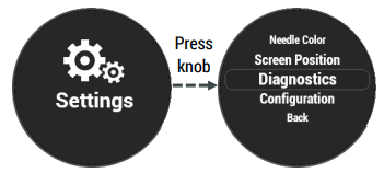
Settings is an item in the Selectable Display. Use the knob rotation and button press to choose this. Refer to the menu map on page 26.
Rotate the knob to scroll through the available menu items and press the knob to select. To return to the previous menu choose Back.
Alarm Messages - Information

Alarm Messages - Caution


Alarm Messages - Critical


*These messages are accompanied by a red blinking bezel border if the park brake is not set and the vehicle speed is less than 5mph.
Menu Map - Selectable Display Menu

Menu Map - Settings Menu

Menu Map - Tire Pressure (TPMS) Setup Menu

Tire Pressure (TPMS) Sensor Display

 The ‘reference pressure’ (Ref. Press.) is established from the current tire pressure. In early versions of the Pressure-Pro system, the ‘reference pressure’ was set as soon as the tire sensor was screwed onto the valve stem. However, in later versions, it is necessary to the use the ‘Update Reference Pressure’ menu selection, refer to page 32.

If tire pressure sensors are moved between towable vehicles with a different number of wheels, it is suggested that only the common front wheel sensors are moved. This allows them to be moved without having to delete and add sensors. However, it may still be necessary to ‘Update Reference Pressure,’ depending on the manufacturers recommend pressures.
Tire Pressure (TPMS) Configuration
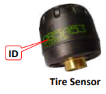
The Tire Pressure Monitoring System (TPMS) consists of multiple sensors which screw onto tire valve stems and communicate to a central module. This module puts the data onto the J1939 network, where it is read by the GIC. The low tire pressure threshold is factory programmed within the TPMS central module. There is an ID printed on each tire pressure sensor, for example OB5A53. Each ID is displayed once it has been added in the TPMS configuration screen.
The TPMS configuration displays 14 tire locations. The last six (6) are for the towable vehicle, where any unused tire locations are shown in a light gray color. This allows all configured tire sensors to be displayed, regardless of the tow vehicle type. This is particularly useful if a tire needs to be moved from a currently unused location to another tire location, because it cannot be added until it is first removed from the original location.
Towable Connected
Refer to the TPMS setup menus on page 28. Press the button knob to toggle between ‘Yes’ and ‘No’

Tow Type
Refer to the TPMS setup menus on page 28. Press the button knob repeatedly to select the number of wheels.

Add Sensor
Select ‘Add Sensor’ just prior to screwing a sensor onto a tire valve stem.
Note 1: If an existing sensor is to be moved to another tire, it must first be removed from the original tire using ‘Delete Sensor’. Refer to page 31.
Note 2: It is not necessary to use ‘Add Sensor’ if a sensor is removed to manually inflate the tire, provided the same sensor is replaced.
Refer to the TPMS setup menus on page 28 (password may be required). Rotate the knob to highlight a menu item and then press the knob to make a selection.
To add a tire pressure sensor:
1. The ‘Towable Connected’ parameter must be set to Yes.
2. The ‘Tow Type’ parameter must be chosen for the relevant number of wheels.
3. If required, enter the password.
Note: This is an independent password entry screen compared to that used for the other configurations.
4. Rotate the knob to select a tire.
5. Choose ‘Add Sensor.’
6. Screw the tire pressure monitor onto the valve stem and wait until its ID is detected. (If required, press the knob to ‘Cancel Add Sensor’)
7. Select ‘Back’ and repeat from step 4 to add additional tire sensors.
8. Refer to page 32 for instructions on updating the reference pressure for each sensor added.
Delete Sensor
‘Delete Sensor’ will remove a sensor from the selected tire location. This is required if a sensor is to be relocated to a different tire. Refer to the TPMS setup menus on page 28 (OEM or service password may be required). Rotate the knob to highlight a menu item and then press the knob to make a selection.
To delete a tire pressure sensor:
1. The ‘Towable Connected’ parameter must be set to Yes.
2. The ‘Tow Type’ parameter must be chosen for the relevant number of wheels.
3. If required, enter the password. Note: This is an independent password entry screen compared to that used for the other configurations.
4. Rotate the knob to select a tire.
5. Choose ‘Delete Sensor’.
6. Repeat from step 4 to delete additional tire sensors.
Update Reference Pressure
Prerequisites: This procedure requires the tire to be inflated to the manufacturer’s recommended pressure because the reference pressure is established from the current tire pressure. It may also be necessary to wait for up to 5 minutes for a pressure sensor to transmit its current tire pressure.
Refer to the TPMS setup menus on page 28 (password may be required). Rotate the knob to highlight a menu item and then press the knob to make a selection. To update the reference pressure for a tire pressure sensor:
1. The ‘Towable Connected’ parameter must be set to Yes.
2. The ‘Tow Type’ parameter must be chosen for the relevant number of wheels.
3. If required, enter the password.
Note: This is an independent password entry screen compared to that used for the other configurations.
4. Rotate the knob to select a tire.
5. Choose ‘Update Reference Pressure’.
Note: Wait for up to 1 minute for the ‘Ref. Press.’ value to display and then wait for up to 5 minutes for the pressure sensor to transmit its next reading for the ‘Pressure’ to display an accurate value.
6. Repeat from Step 4 to update the reference pressure for additional tire sensors.
Diagnostics
The diagnostic screens are found in the System menu. They provide information that is helpful for service staff when troubleshooting any issues, and are discussed in greater detail in the Service Manual.

Smart Wheel Steering Wheel
The SmartWheel Steering Wheel offers control of the horn, headlamp and marker lamp flash, cruise control, and wiper functions from switches mounted on the steering wheel. The system consists of electronic switch pods attached to the wheel and the Control Module mounted in the Front Junction Box. Communication between the steering wheel and the Control Module is accomplished via four wires which utilize a clock-spring in the steering column as a connecting path to allow for wheel rotation. As each switch is closed, the Switch Pod generates a unique signal which is transmitted to the Control Module. The Control Module decodes that signal to determine which switch is closed and operates the corresponding outputs for that function. The same four wires provide power for back-lighting the steering wheel switches.
This section illustrates and briefly describes the switches/buttons mounted on the steering wheel:
1. HORN: Pressing the horn pad on the steering wheel will send the appropriate signal to the Control Module to cause the HORN output to be activated while the switch is pressed.
2. HEADLAMP FLASH: If the headlamps are turned on, pressing the switch will cause them to go off while the switch is pressed. In like manner, if the headlamps are turned off, pressing the switch will cause them to go on while the switch is pressed.
3. MARKER LAMP FLASH: If the marker lamps are turned on, pressing the switch will cause them to go off while the switch is pressed. In like manner, if the marker lamps are turned off, pressing the switch will cause them to go on while the switch is pressed.
CRUISE FUNCTIONS
4. CRUISE CANCEL: Operation of this switch signals the cruise system to disengage without losing the current speed setting.
5. CRUISE RESUME: Operation of this switch actuates the Cruise Resume function of the engine controller.
6. CRUISE ON/OFF: Operation of this switch cycles the Cruise system from On to Off and back again. When the switch is in the on position, the green cruise indicator lamp will illuminate.
7. CRUISE SET: Operation of this switch actuates the Cruise Set function of the engine controller.
WIPER FUNCTIONS
8. WIPER OFF: Operation of this switch causes all operation of the wipers to be canceled. This mode is also entered any time that the ignition is turned off. Activation of any wiper function generates a “Headlamp On” signal from the Master which will only be reset by turning off the ignition, or by activating, then deactivating the dashboard headlamp switch.
9. WIPER WASH: Operation of this switch activates the wash pump relay while the switch is pressed. In addition, if none of the latching wiper functions (Wiper Lo/Hi or Variable) had been previously selected, the Low Speed Wiper will be activated for a period of approximately 3 wiper cycles after the switch is released. If any of the latching wiper functions (Wiper Lo/Hi or Variable) had been previously selected, the wipers will continue to run in the selected mode after the wash switch is released.
10. WIPER LO/HI: Operation of this switch initially causes the Low Speed Wiper function to activate. If the switch is pressed again the High Speed Wiper function will be activated. Subsequent presses of this switch will cause alternate operation of the wipers in the low or high speed mode.
11. WIPER VARIABLE: Operation of this switch initially causes the Low Speed Wiper function to activate for one wipe. If the switch is pressed again within approximately 30 seconds, the Low Speed Wiper function will be activated again and will repeat at an interval determined by the time between the last two operations of the switch. Additional switch operations will shorten the cycle. Activation of any other wiper mode cancels the variable mode. For example, in light rain or mist conditions the driver presses the switch once when the windshield first needs clearing. When the windshield again requires clearing the driver presses the button again – setting the time period between subsequent wipes to that required by current conditions.
RADIO CONTROLS
12. Radio Power
13. Press UP: TOGGLES INPUTS -- PRESS DOWN: RADIO PRESETS
14. (UP/DOWN) RADIO VOLUME
15. (UP/DOWN) RADIO TUNE

