07 Instruments & Controls
GRAPHICAL INSTRUMENT CLUSTER
OPERATION Guide
VDC00027
Formerly VEC13A011-03-OM
Saftety Instructions
WARNING
▶ Driving while distracted can result in loss of vehicle control.
▶ Do not make adjustments in the selectable display on the graphical instrument cluster under conditions that will affect your safety or the safety of others.
CAUTION Your graphical instrument cluster system should be serviced only by qualified personnel.
Overview
The Graphical Instrument Cluster (GIC) is primarily a display device that communicates electronically with multiple pieces of equipment on the coach.
To familiarize yourself with the indicators and gauges, refer to the quick reference guide on pages 6 and 8.
The display will automatically dim for nighttime driving when the headlights are activated.
A selectable display within the tachometer gauge provides a menu system which is navigated by rotating and pressing a joystick knob. Refer to page 26 for the menu selections:
• Speedometer
• Display brightness
• Pre-drive item reminders
• Selectable gauges
• Tire pressure and temperature for coach & trailer
• Trip 1 and Trip 2
With the coach stopped and the park brake applied, the menu also provides the following items:
• Choice of towable trailer/vehicle for the tire pressure monitoring system (TPMS).
• Sound volume for alerts.
• Measurement units for speed/distance, temperature and pressure.
• Background image and brightness.
• Gauge needle color.
• Vertical position of screen display.
• Diagnostics for system, onboard diagnostics (OBD) and controller area network (CAN-Bus).
Cleaning your GIC screen
The glass on the GIC screen is treated with an optical coating to prevent glare and reflection. It should be cleaned with a product that is designed for this, such as the optical wipes included with the screen, or optical cleaner and a microfiber cloth.
WARNING: The screen surface can be damaged if not treated with care.


Navigation
Joystick Knob
The joystick knob is connected directly to the GIC and is primarily used to navigate the selectable display by rotating the knob to scroll the menu or view and pressing to select that item (refer to page 18).

In addition to being pressed or rotated, the top can be levered sideways to the left or right. Do this to toggle between the selectable displays for the speedometer and tachometer.

Indicators


Gauges
Engine Coolant Temperature 
This gauge measures the temperature of the engine coolant fluid. The message center will display a warning and sound an alert when the temperature is higher than the red warning level.
Engine Oil Pressure 
This gauge measures the pressure of the engine oil, which is required to ensure efficient lubrication of the internal engine parts. The oil pressure will increase as the engine RPM is increased from idle to normal driving speed. An oil pressure warning is an indication to seek service at the earliest opportunity.

The message center will display a warning and sound an alert when the pressure is less than the red warning level.
The gauge maximum reading and the low and warning thresholds are factory programmed.
Speedometer
The speedometer displays the speed of the vehicle in miles or kilometers per hour, both with a needle and as a digital readout.
Also found on the speedometer is the fuel gauge, generator gauge, cruise control indicator, and current gear.

Cruise Control
The Cruise Control indicator is gray when the feature is enabled. It is green when the feature is active and a fixed vehicle speed has been set by the operator.
Odometer
The odometer displays the lifetime mileage of the vehicle from when it was manufactured.
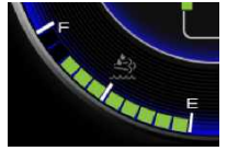
Fuel Level – Engine & Generator
The fuel level is displayed at the bottom of the speedometer. When fuel falls below the factory programmed low level, the fuel indicator will turn red and an alert will sound. The generator gauge is a static gauge that indicates the point at which the generator will run out of fuel.
The GIC is connected directly to the fuel tank level sender. Provided the chassis battery level is greater than the factory-configured ‘Power Off’ level, it continues to send fuel level messages over the RV-C network with the ignition off. This allows the fuel level to be viewed on the Coach Management System for operation of the coach generator.

Note that the generator will run out of fuel before the engine does. As indicated on the gauge, the generator will stop running while there is still an eighth of a tank of fuel left. This provides the operator with the opportunity to drive to a fuelling station.
Message Center
The message center is between the speedometer and the tachometer. During normal operation, this area displays the vehicle logo. When necessary, the message area shows three categories of alarms:
 INFORMATION: These relate to normal operation of the coach. Refer to page 21.
 CAUTION: These indicate items which require your attention. Refer to page 22. A chime may also sound when an alarm occurs.
 CRITICAL: These indicate items which require your immediate attention. Refer to page 25. A chime may also sound when an alarm occurs. When an alarm occurs it is immediately displayed. After a short delay, the display will then continue to cycle through each active alarm.
Odometer/Trip Meter/Fuel Economy
Trip 1 or Trip 2 are items in the Selectable Display. Rotate the knob to display the item. Press the knob to switch between Trip 1 and Trip 2. Hold the knob to reset. Refer to the menu map on page 28.
The odometer displays the lifetime mileage of the vehicle from when it was manufactured.

The average fuel economy and distance to empty can be configured in miles or kilometers. This changes the display between miles per gallon / miles and liters per 100 kilometers / kilometers. Refer to the menu map: Settings > Units > Speed / Dist.
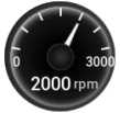
Tachometer
The gauge displays engine revolutions per minute (RPM).
The color of the gauge needle can be configured in Settings > Needle Color.

Diesel Exhaust Fluid (DEF) Level
The diesel exhaust fluid (DEF) level is displayed on the lower left of the tachometer. When the DEF level falls below the factory-programmed low level, the DEF indicator will turn amber and an alert will sound.
The low Diesel Exhaust Fluid (DEF) indicator is illuminated by a message from the engine controller. It has four low level thresholds which determine if the DEF indicator is solid or flashing. Refer to the description on page 12.
Chassis Battery Voltage
This gauge measures the chassis batteries, which are used when driving the coach; for example, starting the engine.

When the voltage falls below 11.5V, the battery indicator will turn red and an alert will sound.
The low and high chassis battery threshold levels are factory programmed.
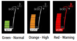
Front and Rear Air Tank Pressure 
The bar gauge color on the front and rear air pressure gauges indicates the following levels:
• Green is normal.
• Orange is slightly low.
• Red is critically low. A warning sound will also occur.

The front air pressure gauge is shown; however, the levels are the same for the rear air pressure gauge.
Compass
The compass displays the direction in which the vehicle is heading.

Outside Temperature
The outside temperature is displayed according to data collected by either RVC (Spyder) or the engine ECU. Units can be changed from Fahrenheit to Celsius in the Settings menu (see page 27).

Selectable Display
There are selectable displays located in the center of the speedometer and tachometer. They are navigated by means of a knob mounted adjacent to the GIC.
Refer to the menu maps on pages 28 & 30. Push the knob to the right or the left to select the speedometer or tachometer. Rotate the knob clockwise and counter-clockwise to scroll up and down the menu items. Press the top button to select that menu item.

Speedometer Selectable Display
The center of the speedometer can display either the current speed or trip information. Speedometer and Cruise Control The digital speed is an item in the Selectable Display – use the knob rotation and button press to choose this. Refer to the menu map on page 28.
With the coach stopped and the park brake applied, you can change also the display units between miles and kilometers with the Selectable Display selection Settings > Units > Speed / Dist.
The color of the gauge needle can be configured in Settings > Needle Color.

Trip 1, Trip 2 and Fuel Economy
The fuel economy is calculated by the engine controller. ‘Inst. Economy’ is the instantanteous fuel economy of the vehicle. For example, when driving uphill, a higher value will be displayed than when driving downhill.
Note: Refer to page 16 for information on the the average fuel economy display.
With the coach stopped and the park brake applied, you can also change the display units between miles and kilometers with the Selectable Display selection Settings > Units > Speed / Dist.

Note: With miles selected, fuel information displayed in US gallons and miles per gallon. With kilometers selected, fuel information is displayed in liters and in liters per 100 kilometers.
Tachometer Selectable Display
The center of the tachometer can display the following:
• Center Gauge
• Pre-Drive List
• Brightness
• Settings
Information Gauges
Information gauges do not have any warning threshold levels.
You may choose to display a single gauge, or select the item to continuously scan through each gauge every five seconds. Scan mode is indicated by the symbol 
The following information gauges are available:
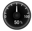
 Accelerator Position - This gauge displays the position of the accelerator foot pedal. 100% is fully depressed.
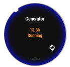 Generator – This readout indicates whether the generator is running, and/or other status information
 House Battery Voltage - The house batteries are used to power items such as interior lights and appliances, thermostats, water pump, furnace, etc. While driving they are charged by the engine alternator; or when parked, with the generator or shore power. Refer to page 17 for information on the chassis battery gauge.
 Transmission Shaft Speed - This gauge displays the revolutionsper-minute (rpm) of the transmission shaft (drive shaft) which is the output of the transmission (gearbox).
Note: The tachometer (refer to page 16) displays engine drive shaft RPM, which is the input to the transmission (gearbox). The difference relates to the current gear selection.
 Engine Load - At any given speed the engine has a maximum torque rating. Engine load is the current output torque as a ratio of this maximum torque.
 Inverter Status – This readout provides the status of the inverter.
 Intake Manifold Temperature - This gauge displays the temperature of the air intake manifold.
 DEF Temperature - This gauge displays the temperature of the fluid in the Diesel Exhaust Fluid (DEF) tank.
During vehicle operation, Selective Catalytic Reduction (SCR) systems are designed to provide heating for the Diesel Exhaust Fluid (DEF) tank and supply lines. If DEF freezes when the vehicle is shut down, startup and normal operation of the vehicle will not be inhibited.
The SCR heating system is designed to quickly return the DEF to liquid form and the operation of the vehicle will not be impacted. The freezing and unthawing of DEF will not cause degradation of the product.
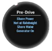
Pre-Drive
Pre-Drive is an item in the Selectable Display. Use the knob rotation and button press to choose this. Refer to the menu map on page 28.
This is an auto-scrolling list which displays active items requiring attention prior to vehicle travel.
After viewing, rotate the knob to select another menu item.
Brightness
The display Brightness is an item in the Selectable Display. Use the knob rotation and button press to choose this. Refer to the menu map on page 28.
Different brightness levels can be set for daytime or nighttime driving. If the headlights are off when the brightness is adjusted, the brightness level will be saved for driving with the headlights off (daytime). If the headlights are on when the brightness is adjusted, that level will be saved for driving with the headlights on (nighttime).

Rotate the knob to adjust the brightness and then press the knob to save for that mode and return to the previous menu.
Settings
The coach must be stopped with the park brake set for this menu item to be available.

Settings is an item in the Selectable Display. Use the knob rotation and button press to choose this. Refer to the menu map on page 28.
Rotate the knob to scroll through the available menu items and press the knob to select. To return to the previous menu choose Back.
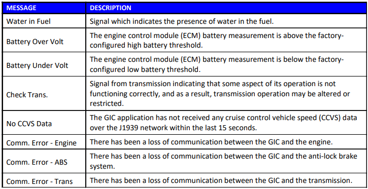
Alarm Messages - Information

Alarm Messages - Caution


Alarm Messages - Critical


*These messages are accompanied by a red blinking bezel border if the park brake is not set and the vehicle speed is less than 5mph.
Menu Map - Selectable Display Menus


Menu Map - Diagnostics
I/O Info System Info
This screen shows the status of the discrete inputs and outputs connected directly to the rear connectors of the GIC.

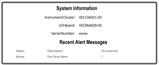
System Info
This screen displays the status of any alert message received since the ignition was turned on. The part numbers, firmware revisions and serial number are also shown.
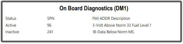
OBD Info
The On Board Diagnostics (OBD) Info displays the status of any diagnostic message (DM1) received since the ignition was turned on.
J1939CANInfo
This displays all devices communicating on the vehicle’s J1939 Controller Area Network (CAN).

RVC CAN Info
This displays all devices communicating on the vehicle’s RVC Controller Area Network (CAN).

Note: Devices communicating on the RVC CAN Bus are always added to this list. No device is removed unless the ignition is turned off to clear the list.
Parts Gallery


Smart Wheel Steering Wheel
The SmartWheel Steering Wheel (Figure 7-4) offers control of the horn, headlamp and marker lamp flash, cruise control, and wiper functions from switches mounted on the steering wheel. The system consists of electronic switch pods attached to the wheel and the Control Module mounted in the Front Junction Box. Communication between the steering wheel and the Control Module is accomplished via four wires which utilize a clock-spring in the steering column as a connecting path to allow for wheel rotation. As each switch is closed, the Switch Pod generates a unique signal which is transmitted to the Control Module. The Control Module decodes that signal to determine which switch is closed and operates the corresponding outputs for that function. The same four wires provide power for back-lighting the steering wheel switches.
This section illustrates and briefly describes the switches mounted on the steering wheel.

1. HORN: Pressing the horn pad on the steering wheel will send the appropriate signal to the Control Module to cause the HORN output to be activated while the switch is pressed.
2. HEADLAMP FLASH: If the headlamps are turned on, pressing the switch will cause them to go off while the switch is pressed. In like manner, if the headlamps are turned off, pressing the switch will cause them to go on while the switch is pressed.
3. MARKER LAMP FLASH: If the marker lamps are turned on, pressing the switch will cause them to go off while the switch is pressed. In like manner, if the marker lamps are turned off, pressing the switch will cause them to go on while the switch is pressed.
CRUISE FUNCTIONS
4.1 CRUISE CANCEL: Operation of this switch signals the cruise system to disengage without losing the current speed setting.
4.2 CRUISE RESUME: Operation of this switch actuates the Cruise Resume function of the engine controller.
4.3 CRUISE ON/OFF: Operation of this switch cycles the Cruise system from On to Off and back again. When the switch is in the on position, the green cruise indicator lamp will illuminate.
4.4 CRUISE SET: Operation of this switch actuates the Cruise Set function of the engine controller.
WIPER FUNCTIONS
5.1 WIPER OFF: Operation of this switch causes all operation of the wipers to be canceled. This mode is also entered any time that the ignition is turned off. Activation of any wiper function generates a “Headlamp On” signal from the Master which will only be reset by turning off the ignition, or by activating, then deactivating the dashboard headlamp switch.
5.2 WIPER WASH: Operation of this switch activates the wash pump relay while the switch is pressed. In addition, if none of the latching wiper functions (Wiper Lo/Hi or Variable) had been previously selected, the Low Speed Wiper will be activated for a period of approximately 3 wiper cycles after the switch is released. If any of the latching wiper functions (Wiper Lo/Hi or Variable) had been previously selected, the wipers will continue to run in the selected mode after the wash switch is released.
5.3 WIPER LO/HI: Operation of this switch initially causes the Low Speed Wiper function to activate. If the switch is pressed again the High Speed Wiper function will be activated. Subsequent presses of this switch will cause alternate operation of the wipers in the low or high speed mode.
5.4 WIPER VARIABLE: Operation of this switch initially causes the Low Speed Wiper function to activate once every 20 seconds. If the switch is pressed again, the Low Speed Wiper function will be activated again and will repeat at an interval of 11 seconds. A third press of the switch will activate the Low Speed Wiper function every 6 seconds. If the switch is pressed again, after reaching the 6 second interval, the time between windshield wiper activation will increase. It will go back to 11 seconds, then 20 seconds, and then off. Activation of any other wiper mode cancels the variable mode.
1ST PRESS = 20 SECONDS
2ND PRESS = 11 SECONDS
3RD PRESS = 6 SECONDS
4TH PRESS = 11 SECONDS
5TH PRESS = 20 SECONDS
6TH PRESS = OFF