07 Instruments & Controls
Tiffin Instrument Panel
The Instrument Panel Assembly (IPA) of the Tiffin Allegro Bus is equipped with Medallion Instrumentation Systems’ Graphical Data Interface Gauge (GDIG). This section briefly describes and illustrates the system.

1. 4N1 Gauge
• Front air
• Rear air
• Oil pressure
• Coolant temperature
2. Speedometer
• Instrument system controller for the Instrument Panel Assembly (IPA)
• Speedometer scale
• Two integral buttons for controlling the LCD
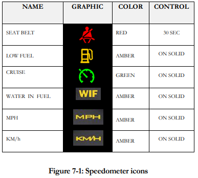
• Speedometer icons (Figure 7-1)
3. 3N1 Gauge
• Tachometer (RPM)
• Fuel tank levels for main fuel tank and generator
• Diesel Exhaust Fluid (DEF) level
4. Chameleon Warning Lamp Assembly (Figure 7-2)


Driver’s Information Center
The speedometer includes a Graphical Drivers Information Center. The functions of the Driver’s Information Center can be broken down into four broad categories:
1. Display of user selectable pre-drive checklist items
2. Display of user selectable driver information screens
3. Display of warning messages
4. Display of utility screens
Pre-Drive Checklist
Note: This option is disabled by default. To activate, press and hold both LCD control buttons simultaneously and the setup menu will appear. Use the left button to scroll down to pre-drive checklist and right button to select. A menu of items will appear for the pre-drive checklist. Scroll to each item using the left button and use right button to change item from off to on. To exit the setup menu, scroll down to exit setup and press right button, or turn the key switch off.
• The Pre-Drive Checklist is displayed immediately following the Tiffin Splash Screen each time the IPA is enabled.
• Pre-Drive Checklist Screens are easily identified by the “Pre-Drive Checklist” title bar across the top of the screen in reverse video.
• Each item in the list must be acknowledged by the operator by pressing either button on the DIG. When acknowledged, the screen scrolls to the next item in the checklist. When all items have been acknowledged, the DIG displays the last Driver Information Screen viewed.
• Edit Function: The checklist items actually displayed at start up shall be user selectable from a master list of items available in the set up menu. You can elect to display all of the items, some of the items, or none of the checklist items as desired.
• By default, the speedometers shall ship from the factory with all Pre-Drive Checklist Item deselected.
• The Master Pre-Drive Checklist Items include:
o JACKS / AIR LEVELER UP
o CHECK TOW VEHICLE
o TIRE PRESSURE
o ENGINE MAINTAINANCE
o DISCONNECT POWER
o DISCONNECT WATER
o DISCONNECT SEWER
o BAY DOORS CLOSED
o SHOWER DOOR LOCKED
o ROOF VENTS CLOSED
o AWINING ARMS LOCKED
o COUNTERTOP CLEAR
o ALL DOORS LOCKED
o DRAWERS LATCHED
o APPLIANCES SECURED
o SLIDES IN AND SECURED
o WINDOWS CLOSED
o CB RADIO ON
Driver Information Screen
1. Driver Information Screens are provided to communicate important information about the vehicle and its performance to the driver.
2. Driver Information Screens are easily identified by the reverse video title bar across the top of each screen clearly identifying what is being displayed.
3. The available Driver Information Screens are:
o Odometer & Gear
o Engine Load
o Transmission Temperature
o Fuel Economy
o Engine RPM
o Engine Hours
o Battery Voltage
Note: The Odometer & Gear Screen may not be disabled and is always available. Other Driver Information Screens may be displayed or not displayed as desired by the driver. The factory default setting is all Driver Information Screens enabled.
Warning Messages
The following conditions will prompt warning messages:
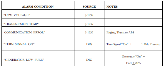
Notes:
1. Each of the above alarms will turn on the “Check Info” Warning Lamp.
2. Each of the above alarms will activate audible alarm 4.
3. Each of the above alarms require user acknowledgement to clear.
Utility Screens
1. The SETUP Menu shall be accessed by simultaneously pressing the left and right display buttons for 3 seconds. When this condition is sensed the Drivers Information Center shall briefly display the word SETUP and then display a list of menu items with the top item in the list highlighted in reverse video.
2. On each utility screen, the function of the left and right display switches shall be displayed in the LCD above each switch.
3. To exit the SETUP Menu, the operator must scroll down the list using the left display button until the EXIT SETUP menu item is highlighted and then press the right display button to SELECT the highlighted action. The LCD shall briefly display the word WAIT as the DIG resets.
4. The following Utilities shall be available in the SETUP Menu:
o UNITS: Pressing the Right Display Button (CHANGE) while the UNITS menu item is highlighted shall toggle the units from English to metric or vice versa. The change shall be immediate and can be confirmed by viewing the speedometer units icons. MPH shall be illuminated when English units are selected and KM/h shall be illuminated when metric units are selected.
o LCD ANIMATION: Pressing the Right Display Button (CHANGE) while the LCD ANIMATION menu item is highlighted shall toggle the LCD Animation State from ON to OFF or vice versa. In the ON state, a TIFFIN MOTORHOMES Splash Screen shall be displayed when the system is starting up and each time the operator scrolls between Drivers Information Screens. In the OFF state, these screens shall not be displayed.
o LCD SCREENS: Pressing the Right Display Button (SELECT) while the LCD SCREENS menu item is highlighted shall bring up a master list of Drivers Information Screens showing the name and the display selection status of each screen (Enabled or Disabled). Pressing the Left Display Button (NEXT) shall allow the operator to scroll to each item in the list. Pressing the Right Display Button (Change) shall toggle the display selection status of the highlighted item from Enabled to Disabled or vice versa. If no button presses are sensed in 5 seconds, the display shall jump back to the SETUP Menu Screen.
o PRE-DRIVE CHECKLIST: Pressing the Right Display Button (SELECT) while the PREDRIVE CHECKLIST menu item is highlighted shall bring up a master list of Pre-Drive Checklist Tasks showing the task name and the selection status of each screen (ON or OFF ). Pressing the Left Display Button (NEXT) shall allow the operator to scroll to each item in the list. Pressing the Right Display Button (Change) shall toggle the selection status of the highlighted item from OFF to ON or vice versa. If no button presses are sensed in 5 seconds, the display shall jump back to the SETUP Menu Screen.
o LCD BACKLIGHT: Pressing the Right Display Button (SELECT) while the LCD BACKLIGHT menu item is highlighted shall bring up a bar graph illustrating the LCD Backlight Brightness setting as a percentage of maximum brightness. Pressing the Left Display Button (DEC) decreases the display brightness and pressing the Right Display Button (INC) increases the display brightness. The change shall be immediate. If no button presses are sensed in 5 seconds, the display shall jump back to the SETUP Menu Screen.
o LCD CONTRAST: Pressing the Right Display Button (SELECT) while the LCD CONTRAST menu item is highlighted shall bring up a bar graph illustrating the LCD Contrast setting. Pressing the Left Display Button (DEC) decreases the display brightness and pressing the Right Display Button (INC) increases the display brightness. The change shall be immediate. If no button presses are sensed in 5 seconds, the display shall jump back to the SETUP Menu Screen.
o ACTIVE FAULT CODES: Pressing the Right Display Button (SELECT) while the ACTIVE FAULT CODES menu item is highlighted shall bring up a list of any active fault codes that are currently being broadcast. The SPN and FMI shall be displayed for each active code. Pressing the Right Display Button (NEXT) shall scroll to the next active fault in the list. Pressing the Left Display Button (EXIT) shall force a return to the SETUP Menu Screen.
o GAUGE DIAGNOSTICS: Pressing the Right Display Button (SELECT) while the GAUGE DIAGNOSTICS menu item is highlighted shall bring up a screen that lists all of the analog inputs to the DIG and their current input voltage expressed as an A/D count. From this screen, pressing either Display Button shall bring up a screen that lists all of the digital inputs to the DIG and their current state expressed as either High or Low. From this screen, pressing either Display Button shall bring up a J1939 VEHICLE DATABUS Screen. From this screen, pressing either Display Button shall force a return to the SETUP Menu Screen.
o IP TEST ROUTINE: Pressing the Right Display Button (SELECT) while the IP TEST ROUTINE menu item is highlighted shall initiate the following sequence of events: 1. The Drivers Information Center shall display the text: IP TEST and alternate between normal and reverse video 2. All six icons in the speedometer shall be illuminated. 3. Light Bar icons shall be illuminated 4. Each gauge shall sweep from zero to mid-scale, from mid-scale to max-scale, and back to zero. This exercise shall be repeated twice. 5. At the conclusion of the gauge exercise the test routine is terminated and the LCD returns to the SETUP Menu Screen.
o SET ODOMETER: Caution: This is a service function used to program a service replacement speedometer. Pressing the Right Display Button (SELECT) while the SET ODOMETER menu item is highlighted brings up a service utility that is used to load the vehicle’s actual mileage should the speedometer ever have to be replaced. Pressing the Right Display Button (CANCEL) returns to the SETUP Menu Screen. This function is locked out when the reading reaches 100 miles.
o GAUGE INFORMATION: Pressing the Right Display Button (SELECT) while the GAUGE INFORMATION menu item is highlighted brings up a screen that displays the revision level and date of the firmware installed in DIG. Pressing either Display Button returns to the SETUP Menu Screen
o RESTORE DEFAULTS: Pressing the Right Display Button (SELECT) while the RESTORE DEFAULTS menu item is highlighted causes all user selections to revert to the factory default conditions of:
• ENGLISH Units
• LCD Animation ON
• All LCD Screens ENABLED
• All Pre-Drive Checklist items OFF After the button is pressed the display automatically returns to the SETUP Menu Screen.
• EXIT SETUP: Pressing the Right Display Button (SELECT) while the EXIT SETUP menu item is highlighted causes the DIG to reset and return to normal operation.
Trip Reset and Average Fuel Economy
You can reset your mileage for Trip 1 and Trip 2. With the odometer screen displayed, press and hold left button to reset trip 1; press and hold the right button to reset trip 2. To reset the average fuel economy, display the fuel economy screen. Push and hold the left button to reset the average fuel economy reading.
Modes of Operation
The Instrument Panel Assembly (IPA) has three operational modes:
• OFF:
In the off state, the following ICONS are still operational:
o Left turn signal
o Right turn signal
o High beam
o Jacks down
All other IPA features are disabled.
• Normal Mode:
The default operational mode is Normal Mode. In Normal Mode, all of the features of the IPA are available to the operator. The gauges, light bar, and driver’s information center are all fully operational.
• Limited Mode:
1. The DIG runs in limited mode when the following conditions are true:
• The Wake Up Signal is high.
• The ignition is off.
• The Park Brake is on.
2. The DIG exits Limited Mode and returns to normal mode when any of the following conditions occurs:
• The ignition is turned on.
• Communication is lost with the VMM module.
• The engine is started.
SmartWheel Steering Wheel
The SmartWheel Steering Wheel (Figure 7-4) offers control of the horn, headlamp and marker lamp flash, cruise control, and wiper functions from switches mounted on the steering wheel. The system consists of electronic switch pods attached to the wheel and the Control Module mounted in the Front Junction Box. Communication between the steering wheel and the Control Module is accomplished via four wires which utilize a clock-spring in the steering column as a connecting path to allow for wheel rotation. As each switch is closed, the Switch Pod generates a unique signal which is transmitted to the Control Module. The Control Module decodes that signal to determine which switch is closed and operates the corresponding outputs for that function. The same four wires provide power for back-lighting the steering wheel switches.
This section illustrates and briefly describes the switches mounted on the steering wheel.

1. HORN: Pressing the horn pad on the steering wheel will send the appropriate signal to the Control Module to cause the HORN output to be activated while the switch is pressed.
2. HEADLAMP FLASH: If the headlamps are turned on, pressing the switch will cause them to go off while the switch is pressed. In like manner, if the headlamps are turned off, pressing the switch will cause them to go on while the switch is pressed.
3. MARKER LAMP FLASH: If the marker lamps are turned on, pressing the switch will cause them to go off while the switch is pressed. In like manner, if the marker lamps are turned off, pressing the switch will cause them to go on while the switch is pressed.
CRUISE FUNCTIONS
4.1 CRUISE CANCEL: Operation of this switch signals the cruise system to disengage without losing the current speed setting.
4.2 CRUISE RESUME: Operation of this switch actuates the Cruise Resume function of the engine controller.
4.3 CRUISE ON/OFF: Operation of this switch cycles the Cruise system from On to Off and back again. When the switch is in the on position, the green cruise indicator lamp will illuminate.
4.4 CRUISE SET: Operation of this switch actuates the Cruise Set function of the engine controller.
WIPER FUNCTIONS
5.1 WIPER OFF: Operation of this switch causes all operation of the wipers to be canceled. This mode is also entered any time that the ignition is turned off. Activation of any wiper function generates a “Headlamp On” signal from the Master which will only be reset by turning off the ignition, or by activating, then deactivating the dashboard headlamp switch.
5.2 WIPER WASH: Operation of this switch activates the wash pump relay while the switch is pressed. In addition, if none of the latching wiper functions (Wiper Lo/Hi or Variable) had been previously selected, the Low Speed Wiper will be activated for a period of approximately 3 wiper cycles after the switch is released. If any of the latching wiper functions (Wiper Lo/Hi or Variable) had been previously selected, the wipers will continue to run in the selected mode after the wash switch is released.
5.3 WIPER LO/HI: Operation of this switch initially causes the Low Speed Wiper function to activate. If the switch is pressed again the High Speed Wiper function will be activated. Subsequent presses of this switch will cause alternate operation of the wipers in the low or high speed mode.
5.4 WIPER VARIABLE: Operation of this switch initially causes the Low Speed Wiper function to activate for one wipe. If the switch is pressed again within approximately 30 seconds, the Low Speed Wiper function will be activated again and will repeat at an interval determined by the time between the last two operations of the switch. Additional switch operations will shorten the cycle. Activation of any other wiper mode cancels the variable mode. For example, in light rain or mist conditions the driver presses the switch once when the windshield first needs clearing. When the windshield again requires clearing the driver presses the button again – setting the time period between subsequent wipes to that required by current conditions.